Krrass customer support team is here to answer your questions. Ask us anything!
Hi, how can I help?
1. 1Foreign cnc press brake have long been hydraulic, and electro-hydraulic proportional (or servo) control technology has been widely used to accurately control the synchronous position, speed and pressure of the two cylinders. Compared with the hydraulic system of the mechanical hydraulic servo valve, it is not only convenient to adjust, high in control accuracy, easy to realize dual-machine combined transportation, but also simple in mechanical structure. The hydraulic system is integrated, and the connection with the numerical control system is simple and convenient, so that the workload of manufacturing, assembly, debugging and maintenance of the bending machine is correspondingly reduced.
1.2 Well-known foreign hydraulic parts companies such as Rexroth-Bosch, etc. can provide a full set of proportional control hydraulic systems for hydraulic press brake. The control valve block (including the filling valve) is directly installed on the top of the cylinder, reducing the hydraulic pipeline to the most modern level. . Well-known companies such as Cybelec, Delem, Autobend, etc. can provide various grades of CNC systems dedicated to bending machines. The above-mentioned hydraulic system and numerical control system can all be matched, which provides great convenience for the bending machine manufacturer. In order to further improve the bending accuracy, some foreign bending machine companies have developed a variety of automatic sheet thickness measurement devices and bending angles. The automatic measuring device, the automatic measuring and compensating device for the springback of the bending angle, have been put into practical use on the bending machine.
1.3 In order to reduce the labor intensity of mold change and shorten the time of mold change. In addition to the universal use of the upper die hydraulic quick clamping device, many foreign bending machines use single die slot die, and the lower die hydraulic quick clamping device is configured on the work table, which not only facilitates the replacement of the lower die, but also ensures the upper and lower die The axis is automatically centered without adjustment. Some bending machines have been equipped with an automatic mold changing device, and a mold library is set on one side of the bending machine to realize automatic mold change.
In order to reduce the labor intensity of the bending operation and realize unmanned operation, several bending machine companies have developed multi-axis CNC special robots and bending machines. Companies have developed multi-axis CNC special robots and bending machines to form a "bending machine". The “bending machine-robot” system realizes unmanned operation when producing typical bending parts with small size and not very complicated shapes.
1.4 CNC has been widely used in foreign bending machines. For example, the Ursviken branch of Pullmax in Sweden produces about 200 bending machines every year, and more than 90% of the products are equipped with CNC. The company's OPTIM type 640KN CNC sheet metal bending machine uses Cybelec's KNC900 CNC system. The company's other new type of bending machine has servo control (with eccentric bending function), a "dual working datum" that can compensate for body deformation during the bending process, and the repeatability can be as high as 0.01mm. The multiple performance of multi-axis control enables effective control of the bending machine. The suspension structure and hydraulic mold clamping device realize automatic mold change quickly, and a sheet thickness measurement device is installed to check the thickness change of the bending plate. Whether it is within the allowable range of the bending machine.
Adira's QH-DNC series all-electric-hydraulic system-controlled upper-drive bending machine adopts Cybelec DNC33P6 system, which all realize DNC control.
1.4 The CNC three-point bending machine of Pacific Press & Shear in the United States has its own characteristics in terms of workpiece bending accuracy and machine operation. The Swiss Hammarler AP series three-point bending machine is the leader of cold processing equipment in the 1980s. It not only has CNC or program control functions, but also solves the problems of high quality and high repeatability of sheet metal bending. . The mold is designed in the form of combined installation of parts. The upper mold is placed on a flexible pressure oil pillow, and the dynamic accuracy of the lower mold can also be adjusted. Therefore, in the multi-level metal sheet bending process, the accuracy of the workpiece is almost independent of the length of the workpiece. Influence. Since the functional relationship or database between the lower die groove attempt and the bending angle of the workpiece is established, these parameters can be applied to the numerical control instructions to control the cold working process program or incorporate it into the flexible production line.
1.5 There is also a flexible bending machine system composed of robots and bending machines abroad, which is used to realize flexible bending. For example, the 5500KNFDB precision bending machine of Japan's Amada Company and the "bending machine-robot" system composed of robots designed by Italian Prima Company. The robot is installed on the workbench of the bending machine, moves along the workbench to the automatic stacker, clamps a sheet of material with the jaws (the sheet has been raised to the same level as the clamp), and returns to its working position , Operate the sheet until all the bending processes are completed, and then return to the automatic stacker to unload the formed workpiece and clamp another sheet.
The bending machine of this design is suitable for bending steel plate thickness 0.5-1mm. Specifically for this bending machine, the material of the processed parts is 08F and the thickness is 0.6mm. Before the bending process, the parts have been processed by the punching machine. Even if the edges of the sheet are folded up to a height of 20mm, there are also some protrusions evenly distributed in the middle of the part, as shown in the figure.
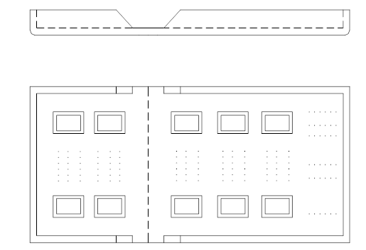
Figure 2.1
After the cnc press brake is processed, it becomes the structure shown in the figure.
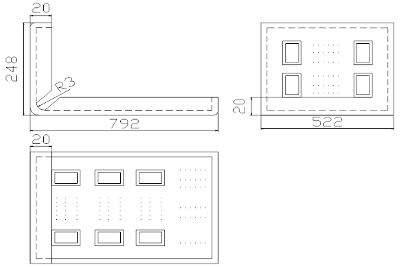
Figure 2.2
Comparing Figure 2.1 and Figure 2.2, we can see that the work to be completed in this design is to fold up the left part of the part shown in Figure 2.1 along the dotted line in the middle by 90 degrees to achieve the shape shown in Figure 2.2. It is required that after bending, the bending radius on the inside of the part is 3mm. At the same time, it can be seen from the part drawing that the processing process is a bending process, and the bending process can be divided into three stages:
1) Elastic bending stage
At this time, the value of the external bending moment is not large, and the stress is less than the yield point of the material;
2) Elastic-plastic stage
On the basis of stage 1), the external stress continues to increase;
3) Pure plastic stage
On the basis of stage 2), as the external stress continues to increase, the material of the blank is completely in the plastic deformation stage.
It can be seen from the parts drawing of the bending product that the function to be realized is to bend the shape shown in Figure 2.1 into the shape shown in Figure 2.2. To achieve this function, there are the following schemes:
Solution (1) Use stamping machine tool to process
Design a special punching machine tool to process, place the workpiece to be processed on the worktable of the punching machine tool, and then process it through the punching head of the machine tool. The processing efficiency of stamping machine tools is high, but because the area of the parts to be processed is relatively large compared with the worktable of the stamping machine tool, the stamping head is also required to be large, and the thickness of the part itself is only 0.6mm, which can withstand the unit area. The pressure is very small, and the parts are easily broken during processing. At the same time, because the sides of the workpiece to be processed have been processed with a height of 20mm, interference will occur during the stamping process, so this solution is difficult to implement.
Solution (2) Use bending machine tool to process
In the scheme (1), in order to process the required parts, the method used is to place the part to be processed on a worktable, and then apply an impulse directly above the part to be processed.
Relative to the solution (1), the solution (2) is mainly to apply a force that is always perpendicular to the part from below the part, so that a part of the part is folded upward into the shape shown in Figure 2.2. Specifically, it is to design a special bending machine, first place the part to the left of the broken line shown in Figure 2.3 on the worktable of the bending machine, and then apply a vertical worktable force directly above the worktable , Press the part tightly on the worktable, and then apply a force perpendicular to the part on the right part of the part, and slowly fold up the right part until it reaches the desired shape (the force during processing is shown in Figure 2.3 ).
Solution (2) improves the problems in solution (1) and avoids applying a large impulse on the surface of the part. It is feasible to make the parts receive uniform force during the machining process without breaking. This scheme can be used to design and process parts.
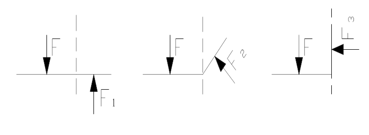
Figure 2.3
Through the analysis, comparison and selection of design principles, combined with the given task book, the approximate outline of the bending machine can be determined. The blank holder force applied on the part is required to be a constant force, and after the processing is completed, the force can be removed for Take away the processed parts, a double-acting oil cylinder can be used as a compression cylinder, and the piston rod of the oil cylinder can be moved up and down to complete the processing. The compression cylinder is fixed on the upper beam, the piston rod is connected with the movable beam, and the movement of the movable beam is driven by the up and down movement of the piston rod (Figure 2.4).
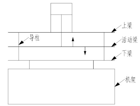
Figure 2.4
Since there is a 20mm high side around the part and the surface has protrusions, the movable beam cannot be directly pressed on the part. Therefore, a compression block must be designed according to the structure of the part to allow the compression block to interact with the part.
The determination of the three-beam and two-column structure of the bending machine provides the blank holder force during the processing. From Figure 2.4, it can be seen that not only the blank holder force is required to bend the part, but more importantly, the bending force is required. The analysis shows that the bending force is required The bending force is always perpendicular to the part during the processing, so a mechanism must be designed to achieve the above requirements through the transformation of the mechanism. Combined with the task book, the force applying body that provides the bending force is the hydraulic cylinder, that is, the bending cylinder. The mechanism can be shown in Figure 2.5.
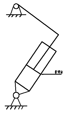
Figure 2.5
The mechanism is a four-bar mechanism with one moving pair, with three rotating pairs and one moving pair, and its degrees of freedom are:
F=3n-2PL=3 x3-2x4=1
The original moving part of the mechanism is a moving pair, which is specifically a bending cylinder for a Press Brake.
Through the determination of the structure of the bending machine and the bending mechanism, the structure of the bending machine and the working process of the bending machine can be determined: that is, the piston of the compression cylinder first moves, pushing the movable beam and the compression block to move downwards until The compression block presses the part and keeps the pressure for a period of time. During the pressure holding process of the compression cylinder, the bending cylinder performs bending processing on the part. After the processing is completed, the piston rod of the compression cylinder moves upward to remove the movable beam and the compression block in order to take away the processed parts.
From the description in this chapter, we can see that to complete the processing of parts, the most important thing is to have a mechanism that can provide pressing force and bending force, and to ensure the coordination of the two forces during the work process.
In the entire design process, the ultimate goal to be achieved is to process a sheet into the shape shown in the part drawing of the product. In the entire design and calculation process, the bending force required to bend the part should first be started. The bending force mentioned here is the bending force in the bending die.
The magnitude of the bending force is not only related to the size of the blank, the mechanical properties of the material, the distance between the fulcrums of the die, the bending radius, and the gap between the molds, but also has a great relationship with the bending method. Therefore, it is very important to calculate the bending force theoretically. Complicated, the calculation accuracy is not high, usually in the production is calculated using empirical formulas or simplified theoretical formulas.
Bending can be divided into free bending and corrective bending. Free bending means that during the bending process, the part being bent is not hindered by the outside; while corrective bending is to apply a resistance to the bending part during the bending process to restrict it. Free deformation of bent parts.
In this design, the bending of the part belongs to free bending. Check the "Stamping Manual" to obtain the free bending force calculation formula of the V-shaped part:

(3.1)is from --- free bending force, the unit is N;
b-----The width of the bending part, the unit is mm;
t-----the thickness of the bent part, in mm;
r-----the inner radius of the bent part, in mm;
σb----the strength limit of the material, the unit is MP;
K------Safety factor, generally take K=1.3. Is N;
Since the material of the plate is 08F, the thickness of the material is a=0.6mm. Check the "Stamping Manual", the minimum bending radius corresponding to 08F is divided into two cases: when the bending line is perpendicular to the rolling direction, rmin=0.4t (T is the thickness of the material); when the bending line is parallel to the binding direction, rmin=0.8t. Also, because it is difficult to know the distribution of the binding during the processing, it is assumed that the bending line is parallel to the binding direction in the plate, so: rmin=0.8t
(3.2)rmin =0.8×0.6=0.48mm
At this time, the layer of rmin is the neutral layer of material deformation, which is also the smallest radius that the material can bend. In this design, the inner radius of the part after bending is 3mm, which is greater than the smallest radius of bending. Processing. The minimum bending radius rmin and the structure after bending are shown in the figure.
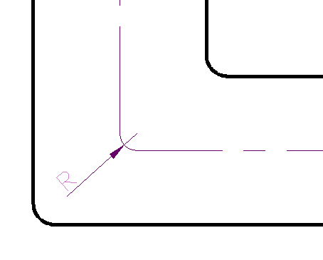
Figure 3.1
From the part drawing of the bending product, it can be seen that the width of the plate is b=522mm, the thickness t=0.6mm, and the inner radius of the bend is r=3mm. The strength limit σb of the parts that can be checked in the Mechanical Design Manual is not less than 295MP, and σb is taken here. =295MP. Then the free bending force of the material is obtained by formula (3.1):
 N
N
The above is the solution process of the bending force, that is to say, in the process of bending the part, the force that the cylinder finally acts on the part through the transformation of the bending mechanism cannot be less than 12011.2N.
3.2.1 Design of compression block
According to the principle of the bending machine, it is known that to bend a part, a pressing force must first press the part and then process it. The length of the part that is always on the plane of the worktable is 792mm and the width is 522mm. There are sides with a height of 20mm around, so the length of the compression block is designed to be 520.8mm so as not to touch the parts. From the front view, make the planes on the front and rear sides of the compression block aligned with the planes on the front and rear sides of the movable beam, and the task book requires the effective area of the workbench to be 550mm*250mm, then the width of the compression block is 300mm. In addition, there are some protrusions in the middle part of the part, so the lower part and one side of the compression block should be dug out with a depth of 5mm. When processing this part, it can only be processed by a milling machine due to structural limitations. After the part is bent, in order to prevent the protrusion of the folded part from interfering with the compression block, a groove with a depth of 5mm and a width of 490mm should be opened on the side of the compression block. In general, let the compression block
Squeeze the three outer sides of the part. At the same time, due to the special structure of the part, the intersection between the height of the two sides before bending and the vertical plane is an arc with a radius of 3mm, and the bending radius after bending is also 3mm, so the compression block is required to intersect both sides of the part at the same time. The contact area is also processed into an arc with a radius of 3mm. Also, because the parts to be bent are only 0.6mm thick, the precision requirements of the compression block are very high, so when assembling the compression block and the movable beam, it should be equipped with positioning pin holes. When determining the position of the positioning pin hole, the greater the linear distance between the two holes, the better, which can reduce the positioning error, and at the same time, the positioning pin and its hole should be an interference fit. The specific structure of the compression block is shown in Figure 3.2. The specific structural dimensions are shown in the parts drawing of the compression block.

Figure 3.2 Schematic diagram of the compression block structure
3.2.2 Calculation of blank holder force
In 3.2, the structure of the compression block has been designed, and the calculation of the blank holder force can be found in the "Stamping Manual": the blank holder force, that is, the blank holder force, is 30% to 80% of the V-shaped free bending force, that is,![]() .
.
(3.3)![]() Is the pressing force, the unit is N;
Is the pressing force, the unit is N;
![]() Is the free bending force, the unit is N;
Is the free bending force, the unit is N;
The calculation formula of V-shaped free bending force is:![]()
(3.4)K is the coefficient, the unit is mm, generally 0.3-0.6
b is the width of the bent part, in mm.
t is the thickness of the bending part, the unit is mm.
σb is the bending strength of the bending part, the unit is MP
From the part drawing of the bending product, it can be seen that the width b=522mm and the thickness t=0.6mm of the plate. The strength limit σb of the parts that can be checked in the "Machine Design Manual" is not less than 295MP, and σb=295MP is taken here. Then the free bending force of the material is obtained by formula (3.4):
![]() N And because there are:
N And because there are:![]() Taking the median value, the blank holder force is:
Taking the median value, the blank holder force is:![]() The above is the process of solving the blank holder force. Specifically, during the working process of the bending machine, the bending process must be successfully completed, and the blank holder force acting on the part through the force transmission of the pressing cylinder cannot be less than 27718.2 N.
The above is the process of solving the blank holder force. Specifically, during the working process of the bending machine, the bending process must be successfully completed, and the blank holder force acting on the part through the force transmission of the pressing cylinder cannot be less than 27718.2 N.
![]()
Masters in industrial manufacturing with 25 years of experience and 10+ awards!