Krrass customer support team is here to answer your questions. Ask us anything!
Hi, how can I help?
Warning!
When using the machine, basic safety precautions should always be followed to reduce the risk of fire, electric shock and personal injury.
Read all instructions before attempting to operate this machine and keep these instructions.
Safety notes!
Error operation may cause die or serious injure.
Fault operation may cause mid-grade harm, flesh wound or damage.
There are emergency stop buttons on the handle control station. When there happens error operation or other accidents, push the emergency stop button, the machine will power off.
Catalogue
Introduction!
We suggest all users and operators to read this operation manual carefully before using this machine.
This manual is designed for specialized and qualified personnel. It comes completes with diagrams and all the documentation necessary to lift, move and place the machine and instructions for the safe use and maintenance of this machine. All information contain in here are accurate at the time of print. However, our company reserves the rights to modify and improve specifications without prior notice.
This machine should be properly installed as instructed; regular inspection and faithful maintenance service should be carried out so that good performance can be maintained.
Any incorrect and irresponsible usages may cause irreparable damage to the machine and nullify the safety protection for the operator.
We do not assume any responsibility for improper services or modifications or connections made by unauthorized personnel.
We suggest that all users to read and understand this manual before using this machine.
The electro hydraulic servo numeric-control press brake is high-efficiency and high-precision in bending sheet metal. The opening size of V-gutter on lower dies, usually larger than eight times of the sheet thickness, should be regulated for sheets in different thickness. Using different kinds of upper and lower dies can bend all kinds of work pieces. And see the Sheet of Bending Brake (on the body of machine) for desired bending force or calculate out the bending force using bending formula. One slider travel makes a sheet bending and the complicated shape work piece may be achieved through bending many times.
The machine is structured in steel plate fabrication with sufficient strength and rigidity. The hydraulic drive prevents the machine from serious overload operation accidents caused by the change of sheet thickness or bad choice of lower die cavity. Additionally, this machine is also featured by the steadiness of work, convenience of operation, and reliable safety. The connecting section to the upper die is provided with compensation device, which compensates the deflection of worktable and slider in bending and guarantees the high work precision.
It is equipped with hydraulic electric control, freely adjustable slider travels and inching operating criterion convenient for module trial and adjustment.
This machine is advanced in technology and reliable in performance, and among the ideal shaping apparatuses. It is widely used in plane, automobile, shipbuilding, and machine with high production efficiency.
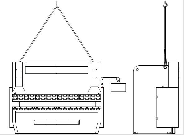
4.1 Hoisting of Machine
Given a high center of gravity, this bending brake is heavy in the front and light in the rear. So attention must be paid to the center of gravity in order to avoid the turnover of machine. Silk ropes should be used at small included angle to assure the consistency of machine.
4.2 Installation of Machine
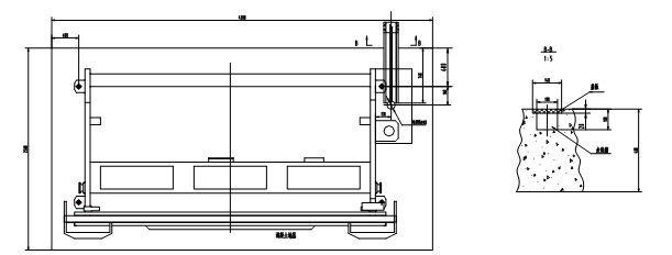
The basis of concrete must have been done 10 days before installing the machine, and the depth of concrete must up to 400mm, according to the Fig. 2 to confirm the position of basis.
4.3 Clear up
Before running the machine, must get rid off the rust protection oil on the following moving parts.
---the surface of piston pole
---surface of slider raster guide rail
---the surface of guide rail, axis, supporting on the bake gauge
---the surface of slider guide rail
---the surface of worktable and mould set
Note: Permit to use gasoline and coal oil to clean, prohibit using dissolvent wash.
4.4 Level
Note: Place the machine on the horizontal underlay. To do the precision adjustment after all parts of machine are connect well including electrical parts. The process is: set the slider block on the upper dead spot, set a gradienter (precision is ±0.05mm/m) on the two sides of slider blocks, adjust the vertical level. The horizontal level adjustment set a gradienter (precision is ±0.05mm/m) in the middle of worktable, and in all this process, the bottom screw must be connected well.
Note: The level must be check and adjust again after using for 30-50 hours.
4.5 The connections of electric
After main switch (power phases: R, S, T, PE) coupling, check the hydraulic pump orientation through short testing start. If the orientation is wrong, cut the power right away, and exchange the two phase-lines (see the hydraulic pump moving arrowhead).
The cable entrance set on the bottom of electric box.
Note: (1) Confirm the voltages are matching.
(2) Make sure to let the expert of electric or expert according the manual to instruct person to do the electric connection of machine.
The machine is gathering with numerical technology, servo and hydraulic, upper crossbeam through the movement of control valve to carry out moving up and down periodically, the measure of movement read by the rasters at two sides of the machine.
DNC control the hatches of two valves in left and right oil cylinders. If need, the flux in oil cylinder can be reassigned by servo, make the upper crossbeam to move straight on vertical orientation, and the measure of movement is decided by new measured pulse number. (Fig. 3)
Operating unit Safety control DNC control
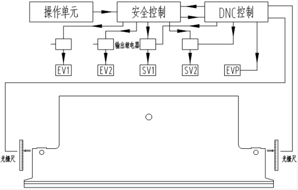
Fig. 3
The signal from the DNC controller through the servo valve to come to the hydraulic pressure signal and control the movement of valve, each cylinder all has its own independence control loop in the hydraulic system, as well as the servo valve and the filling valve.
6.1 The definition of axes
Through DNC to control axes
Left oil cylinder of slider block: Y1
Right oil cylinder of slider block: Y2
Lower crowing table: V
The back gauge moving front and bake: X
Note: The position of slider block can be programmed by equation of absolute value and size of angle.
Manual adjusting Z1, Z2, R1, R2
6.2 The position and character of each axis
| Axis | Zero position | Actual numerical value |
| Y1 left slider block(up or down) | Surface of worktable | Distance between surface of worktable and mould of slider block |
| Y2 right slider block(up or down) | Surface of worktable | Distance between surface of worktable and mould of slider block |
| X、X1、X2 back gauge〔front and back〕 | The center of lower die | Max distance between center of upper die and back gauge |
| R、R1、R2 back gauge(up and down) | Surface of worktable(and the lowest spot of back gauge) | The distance between surface of worktable and the lowest spot of back gauge |
| Z1 the left of back gauge〔left to right〕 | Left of machine body | The distance between the most left side of machine body and left end of back gauge |
| Z2 the right of back gauge〔right to left〕 | Left of machine body | The distance between the most left side of machine body and left end of back gauge |
Note: (1) According to the DNC manual operation to do the programs of axes
(2) The left and right in the table means we face the front of machine.
Warning: (1) The operator should pay attention to the position of back gauge, if it through the area of mould, the machine will be damaged.
(2) When adjusting the Z axis manual only allow to do it from the back of machine.
(3) Must be careful when adjusting back gauge to avoid hit the lower die.
The back gauge is supported by straight-line guide and ball bearing lead screw, it composes by a beam from one side of machine to another side, and the guide of back gauge equipped on the two sides of machine body, behind has free moving working space, X to moves the part by the DNC control, the back gauge is driving by servo motor.
7.1 Hydraulic pressure oil box
The hydraulic pressure oil box welded inside of the machine body, the inhaler equipped on it, and the motor, oil pump, high pressure valve, control valve and electron system are equipped outside, the filtrating core and valve pedestal are equipped on the peak, discharging oil screw equipped on the bottom of oil box.
7.2 Electric motor
3-phase four-grade motor
7.3 Oil pump
High pressure gear pump and main motor connected by flexibility joining shaft.
7.4 The inhaler
The grade of filtration is 10μm, and max pressure is 400bar, when the filter was jammed or change the oil, the filter must be instead.
7.5 Synchro servo valve
The servo valve is equipped on the top of oil cylinder; its flux is controlled by DNC numerical control system and servo amplifier, then control the slider block speed in the whole travel range, the position and manner it can control as follows:
Moving quickly
Bending speed
Lower dead spot
Return travel
Upper dead spot
7.6 Fill in valve
It’s on the top of oil cylinder, when the slider moving quickly, the oil in the oil box through the fill in valve flow in the oil cylinder, it’s closed when bending.
7.7 Pressure valve
The pressure valve is on the servo valve, back pressure when adjustable return travels.
The over travel protection controlled by DNC, the DNC check the time and pressure oil way of over travel when start. This is also called oil pressure leaking checking.
9.1 Note: 1st, before the manufacturer orders all machine tool parameter has all established, these parameters can guarantee the operation security.
2nd, the machine tool parameter change, only then to carry on after obtained the manufacturer notice
3rd, when the 2nd request cannot obtain observes, can cause the machine tool parameter change, creates the equipment accident.
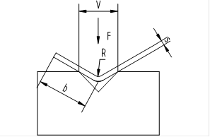
Fig. 4 The sketch map of lower die
F: The requiring bending force (KN/m) of per meter when the material tensile strength is 400 N/mm.
If the material tensile strength is 800N/mm, the requiring bending force (KN/m) of per meter doubles.
S: Plate thickness (mm)
B: Minimum bending width (mm)
V: The width of lower die opening (mm)
R: The bending half diameter (mm)
V width of V lower die must determinates according to the material thickness S and the general formula is:
S<3mm V=(6~8) ×S
S>3mm V=(8~12) ×S
At the same time, min bending width and bending angle are changed, only this, can determinate the limit of lower die overall dimension scientificly.
| s | v | F | r | b |
| 0.5 | - - 8 | - - 28 | - - 1 | - - 4 |
| 1 | 8 8 10 | 110 80 70 | 1 1.2 1.5 | 4 5 6 |
| 1.2 | 8 10 12 | 120 100 80 | 1.2 1.5 1.8 | 5 6 7 |
| 1.5 | 10 12 16 | 150 130 90 | 1.5 1.8 2.4 | 6 7 9.5 |
| 2 | 12 18 20 | 220 170 130 | 1.8 2.4 3 | 7 9.5 12 |
| 2.5 | 18 20 24 | 250 210 130 | 2.5 3 3.6 | 9.5 12 15 |
| 3 | 20 24 32 | 300 250 190 | 3 3.6 4.8 | 12 15 20 |
| 4 | 24 32 40 | 440 340 270 | 3.6 4.8 6 | 15 20 25 |
| 5 | 32 40 50 | 550 420 320 | 4.8 6 7.5 | 20 25 32 |
| 6 | 40 50 60 | 600 480 400 | 6.5 8 9.5 | 25 32 38 |
| 8 | 50 60 80 | 880 720 530 | 8 10 12.5 | 32 38 51 |
| 10 | 60 80 100 | 1100 850 570 | 10 13 16 | 38 51 62 |
| 12 | 80 100 120 | 1200 960 800 | 13 16 19 | 51 62 73 |
| 14 | 100 120 140 | 1310 1090 980 | 15 18 21 | 62 73 85 |
| 15 | 100 120 140 | 1500 1250 1070 | 15 18 21 | 62 73 85 |
| 16 | 120 140 160 | 1420 1230 1070 | 18 21 24 | 68 79 90 |
| 18 | 140 160 180 | 1545 1350 1200 | 21 24 27 | 87 100 112 |
| 20 | 140 180 200 | 1900 1700 1350 | 25 28 38 | 85 98 121 |
| 25 | 180 200 250 | 2550 2100 1700 | 28 38 41 | 100 121 131 |
| 30 | 200 250 300 | 3000 2550 2100 | 38 41 53 | 125 131 143 |
In the bending process, the bending force will flock together on the worktable surface, and function on the tooling at the same time, so the burthen of tooling can bear should not overload.
For example:
S=2mm
F=150KN (15t/m)
B min=10mm
R=2mm
Selecting lower die is V12, V16, V20, when selecting V16 lower die should try to according the thickness of plate.
F=170KN (17t/m)
B min=9.5mm
R=2.4mm
Relatively, the half diameter is not very important, and when b>Min bending half diameter, different thickness plate can do on the same lower die.
V16 S= 1.5mmm, 2mm, 2.5mm
Note: If it’s the tooling molding, the bending force must be 2 times or 3 times
FP= (2....3)Fb
9.3 Selection of upper die
The selection of upper die also need to according to the bending force and the limit burthen can not be over loaded.
In addition, customer can choose the special tooling and should pay attention to the burthen which is different from the standard tooling.
Note: In the dangerous area of the machine, the operator must abide the safety principle, Fig.5, Fig.6.
A, Forbid passing through the tooling
B, In order to avoid accidence, before equipping the upper and lower dies, should se t the starting button on the second control position and NC driving button to “axes stop”.
Equip the lower die and adjust the clamping bolts.
Move the slider block slowly until the distance between slider block and lower die is about the thickness of plate.
Fix the upper die and upper die pedestal, and then set it on the slider block, screw the clamping bolts slightly or close the part of clamping.
Using little force to press the mould in harness, the center of upper and lower die must be at a straight line. After one side of the mould edge totally connected, screw down the clamp part.
9.4 The material of sheet metal
The table below only for reference, if there are questions, check the processing material.
| Type | Tensile strength Kg/mm2 | |
| Aluminum | Soft rigidity | 10.5 |
| Middling | 13.3 | |
| High | 19.6 | |
| Brass | Soft | 32.9 |
| Mennir high strength resists corrosion the constantan | Middling | 42 |
| High | 59.5 | |
| Copper | 扎制 | 25.9 |
| Chromeplate Aluminum | soft | 24.5 |
| Heat treatment | 38.5 | |
| Iron | Wrought iron | 35 |
| Steel | 0.25%c | 46.9 |
| 0.5%c | 66.5 | |
| 0.75%c | 80.5 | |
| 1.0%c | 91 | |
| 1.2%c | 105 | |
| 1# Volume steel | 52.5 | |
| Stainless steel 18-8 | 66.5 | |
10.1 The impossible faults and resolve methods
Note: (1) Make sure the starting will not make any harm before starting.
(2) The machine tool must under the condition of safety and suitable for working to run, all the protector and safety measure must be positioned.
(3) Avoid any dangerous operation referring to safety.
(4) Once appears faults should stop the machine and remove the fault right away.
(5) Resolving faults must be instructed under the suffice fitter people or expert.
(6) Normally, check whether there is damage or fault from the outside of the machine and report it, stop the machine if necessary.
(7) The operator must carefully read the operation manual
10.2
| Failure | Reasons |
| Press engine can not moving quickly | Guide rail move spang, exchange valve EV1/2 damaged, control valve SV1/2 damaged |
| Press engine can not produce pressure | Exchange EV1/2 didn’t working, filling in valve V5/6 opened, pressure adjustment damaged, pump wear and tear |
| The press engine stop at the stopping position for 5-10 seconds then do slowly movement | Filling in valve EV5/6 closed, oil position is too low in the oil cylinder |
| The press head moving back slightly first then start slowly | Single valve V11/V12 opened, the setting parameters wrong |
| Bending not correct | Control valve failure, basic setting wrong, transducer doesn’t adjust well, or transducer damaged. |
| The press head can not go back, the press head go back slowly | Control valve SV1/2 damaged, exchange valve Ev1/2 have no response, filling in valve jammed at the closing position, single valve EV9/8 at the closing position, pressure adjustment valve EVP damaged, wrong parameter setting, guide rail move spang, stroke pressure is too low. |
| The press head stopped at the high position, up to 2-3mm go back, slowly move down and the speed not exceed 2mm/min | Single-way V7/8 opened, exchange EV1/2 leak or plug |
Note: we require the competent person to solve the possible failure, and abide the inspection technology rule, in the warranty period, should notice the maintenance people, if the failure caused by wrong operation, the maintenance people will not suffer any duty.
10.3 The maintain of machine
Note: 1. before the machine working, it’s important that the tooling match the control program
10.4 Stop the machine after working
Two ways of stop
(1) Stopped at the center of lower dead spot
---Slider block move to the center of lower dead spot
---Close the main motor
---Set the operation selecting switch to “0”
---The main switch set to “0”
(2) Use two same height wood to stop (Using for maintain period)
---Place the two wood on the worktable
---Rotate the “operation selecting” key switch to “2” (asjustment)
---operate as the “manual”
After the machine stopped, move the slider block down manual until it connecting the wood slightly.
---Close the main motor
---Set the operation selecting switch to “0”
---The main switch set to “0”
10.5 Use the emergency stop button
When use this button, all axes stop and the pump closed, while the control system will not close.
Restart the machine:
---Release the emergency button
---Press the green light “run the main motor” button.
Don’t need to restart the machine tool
10.6 Proofread the slider block
In case of stop, one side of the slider block inclined or lower than the level position, can adjust manual, but need to off the machine, and then start it at the normal condition.
Note: If the slider block can not be proofread or the position function is closed for several times, this can determinant the control system or hydraulic system failure.
11.1 Request
(1) The maintaining and testing person must read this operation manual and full of experience.
(2) Suggesting letting the manufacturer of this machine to have a check to this machine
(3) The operator of the machine must do the checking everyday to the impossible leaking and loosing parts.
(4) If the fault can not resolve by the user, should notice the manufacturer right away.
11.2 The maintenance instruction of the machine parts.
Checking weekly
Guide way: Lubrication
Back gauge: Lubrication
Checking the loosing and tight of the driving belt
Checking the parallel
Clear the index plate
Checking the driving parts
Moulds: Clean and check the damage
11.3 The maintenance instruction of hydraulic system
Fill in the hydraulic oil:
Check the position of the oil everyday, when the slider block on the top, observe the oil position meter, if need, fill in oil.
Filling oil exceed the 10% of the oil box cubage, must let the hydraulic oil circulating for single way, the time can calculate by the oil box cubage and the circulating frequency of hydraulic pump.
When the slider block is at the upper dead spot, adding the oil to the middle of oil staff gauge (from the back of oil box can see it).
T------Circulating time (minute)
V------Oil box cubage (litre)
Q------ The circulating frequency of oil pump
High-power filter
After working for 200 hours, the filter core must be instead for the first, after that, instead it every 6 months or after working 1000 hours, or the yellow indicator light “instead the filter” bright. Filter net request the 10U, after exchanged the core, the oil must be circulating working more than 1 hour as the mentioned above.
Note: After the yellow indicator light “instead the filter” bright, must change the core in 8 working hours.
Back gauge
If need, all the axes zero position of the machine which the back gauge without localizer, must be checked once a week or get the compensation from DNC.
11.4 Inspection of machine function
Inspection of carry measure system
The parts of machine
Adjustment inspection
Inspection of all screw connection
Rail way inspection
Inspection of transducer signal transfer
Inspection of slider block tighten parts
Inspection of back gauge driving parts
Inspection of back gauge tighten parts
Inspection of mould adjustment
Inspection of bending different plates (thickness)
11.5 Inspection of checking valves
The checking valves V7, V8, V9 and V10must be inspected for every six months, and the inspecting ways are as follows:
----V7/V8
------moving the slider block to the upper dead spot
------Get away the connecting pin single-way EV1, EV2
------Run two manual control switches
------The checking valve must prohibit the oil from the bottom of oil cylinder through servo valve flow to oil box. (Slider block must stop at the upper dead spot)
------If the slider downhill, should ask the manufacturer to change the valve.
----V9/V10
----- moving the slider block to the upper dead spot
-----Close the switch
-----Run the single-way valve EV1 and EV2 though the pin on the end cover
-----The moving speed of slider block should nearly 10mm/s
-----If the slider block moving down quickly, should exchange the relevant valve
Note: The checking valves mentioned above are the part of safety system, before exchange the potential damage valve should not start the machine tool.
Inspection of the pressure adjustment valve
The safety seal ring of mechanical pressure adjustment valve must be inspected once every year.
Note: If can not do the adjustment above, any claim for compensation of quality problem in warranty period is inefficacy.
11.6 Replacing the oil
------Hydraulic oil must be exchanged for every three years or after working 6000 hours
------Moving the slider block to upper dead spot and support well
------Adjust the screw to egest hydraulic oil
------Filling in new hydraulic oil to the middle position, and let the slider to stop at the upper dead spot
------Before restart the machine, make the hydraulic oil circulating about one hour.
------After circulating, reinsert a 10um filtrate core
Commending hydraulic oil and lubricant
| Manufacturer | Hydraulic oil | Grease |
| ESSO | NUTO H46 | BEACON EP2 |
| SHELL | TELLUS 46 | ALVANIA EP2 |
| GULF | HARMONY 46 AW | CROWN EP2 |
| BP | HLP 46 | LS2 |
| FEXACO | RANDO OIL 46 | MUTIFAX EP2 |
| MOBIL OIL | MOBIL DTE 25 | MOBIL LUX EP2 |
![]()
Masters in industrial manufacturing with 25 years of experience and 10+ awards!