Krrass customer support team is here to answer your questions. Ask us anything!
Hi, how can I help?


While using this manual, you will come across the signs and icons represented here below: they are directly related to the safety and security of persons. Carefully follow this advice and inform others about it.


Depending on software evolutions and the press brake controlled by the CybTouch (configuration/capabilities), the present manual may not fully correspond to the CybTouch that you currently have. However, differences are only minor. Touchscreens are pressure sensitive. Do not press down hard on the screen.
Pressing hard on the screen will damage the display. Such damage is not covered by manufacturer warranty!
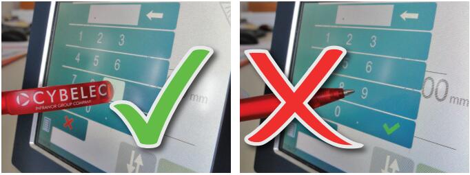
Do not use sharp and/or pointed objects (sheet metal, screwdriver, metal pen ball, etc.) to touch the screen; only use your fingers (with or without gloves on) or a plastic pen. Make sure that your gloves do not have metal particles encrusted in the finger tips as they may also damage the screen.
Take a few minutes to practice pressing gently on the screen, you will find that the screen is very reactive and it is pleasant to use.
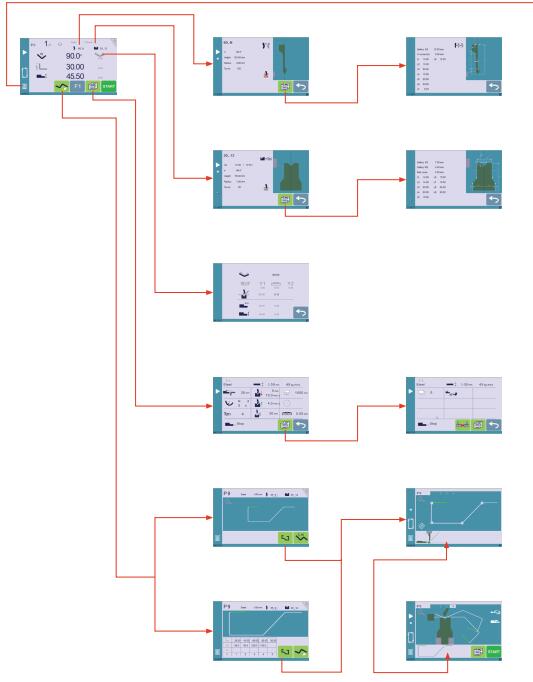
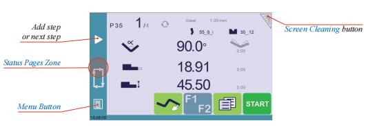
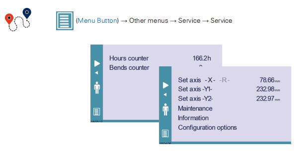
The Menu button ![]() allows you to directly select (jump to) the desired screen. The content of the menu changes contextually.
allows you to directly select (jump to) the desired screen. The content of the menu changes contextually.
The Status pages zone gives access to the Status page (see page 7). This is really a zone that is active at any moment from any page.
To clean the screen while the CybTouch is on, touch the ![]() button. Use only a damp and smooth cloth with soap or a neutral detergent.
button. Use only a damp and smooth cloth with soap or a neutral detergent.
NEVER use solvent, petrol, benzene, alcohols, etc.
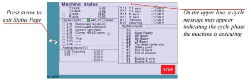
The Status page shows the status of all inputs and outputs and axes positions of the NC.
This feature is very useful during setup or during phone service with a machine installed in the field.
This page is accessed from anywhere by pressing the Status Pages Zone (see page 6).
To exit the Status page, press on the arrow on the left.
To exit the User Preference page, touch the ![]() button
button
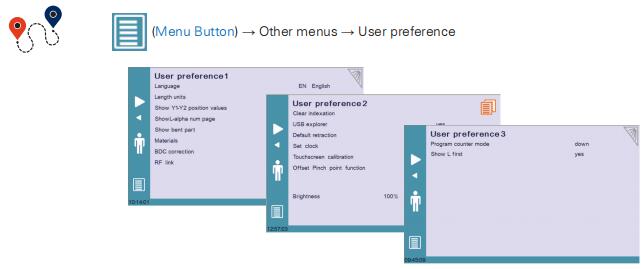
To browse through the available languages, simply touch Language on the screen. Available languages are:
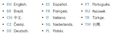
The list of available languages is subject to change and may increase over time.
This parameter allows choosing between mm, inch and none for the length unit to be used in the CybTouch.
When none is selected, the units used are millimeters.
This function will display the axes positions on the Bend Numerical Page (see page 17). • When set to no, the position of axis Y1 is displayed during the beam’s movements.
• When set to yes1, the positions of the axes are displayed during their respective movements.
• When set to yes2, the positions of the axes are constantly displayed under their respective set-point values.
This preference is only available if the machine is equipped with the TouchProfile Mode (optional) option. When set to yes, this parameter gives access to the L-Alpha Mode . This button ![]() is then displayed on the TouchProfile Mode (optional) page.
is then displayed on the TouchProfile Mode (optional) page.
This preference is only available if the machine is equipped with the TouchProfile Mode (optional) option. This parameter, when activated, lets the operator see the state of the part before and after the bend in the Manual Bend Sequencing page.
Touching Materials opens the Materials page, where the default characteristics for each material can be changed, or a new material can be configured.
This page may not be available, depending on the machine parameters’ configuration. To be allowed to access the Materials page, a level 2 password is required.
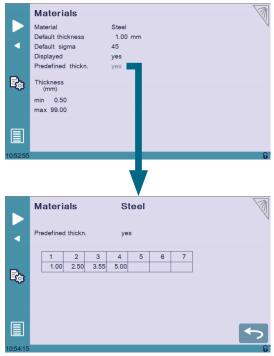
The Materials page displays:
• Material: Selected material (here Steel).
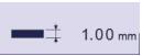
• Default thickness for the material.
• Default sigma: Default sigma for the material (here 45).
• Displayed: If the material will be available to be selected for use (here yes).
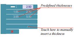
• Predefined thickn.: Allows defining up to 7 different predefined thicknesses for the selected material.
• Thickness min/max: Determines the maximum and minimum accepted thickness for the selected material.
Three predefined default materials are available (steel, stainless steel, aluminum), but others can be added.
To add a material:
1. Touch Material and select a non-configured material (Mater X) from the list.
2. Enter the new material’s characteristics.
3. Touch the name (Mater X) to display the keyboard and enter the name of the new material.
When activated, this function clears the index and the machine will search for them, as it does when turning the power on, allowing the operator to re-index its machine without turning it off.
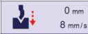
When this parameter is set to yes, it is possible to browse the USB key from the USB transfer screen. Default retraction This parameter allows defining the default value displayed in the More Page when activating the back gauge retraction function.
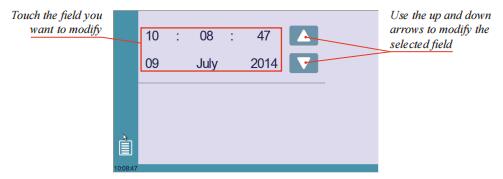
Allows the user to set the time and date on the CybTouch.
As a tall operator will tend to touch higher than a smaller one on the screen, this function allows the calibration of the touch screen, and also makes sure that it is operating correctly.
As a tall operator will tend to touch higher than a smaller one on the screen, this function allows the calibration of the touch screen, and also makes sure that it is operating correctly.
Setting Instructions:
Simply follow the instructions on the page to calibrate the touchscreen.
Use your finger or the plastic tip of a pen to calibrate the Touchscreen. Never use sharp objects as this will damage the screen.
When this parameter is set to yes, the Offset Pinch Point (see page 23) function is available on the More Page.
Here the brightness of the screen for normal mode and Eco mode can be defined:
1. Touch the mode for which you want to modify the brightness.
2. Use the ![]() buttons to set the brightness.
buttons to set the brightness.
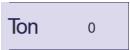
This parameter allows defining the counting mode of the part counter. When set to up, the counter will count up to the desired number. When set to down, the counter will count from the desired number down to 0.
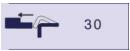
This function allows choosing the data entry mode for the back gauge on the Bend Numerical Page or EasyBend Page. When set to yes, the length of the flange icon ![]() is displayed by default. When set to no, the icon for the position in mm of the back gauge
is displayed by default. When set to no, the icon for the position in mm of the back gauge![]() is display
is display
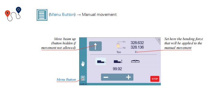
In the course of setting up a machine, it is sometimes necessary to be able to move the axes manually, for example when changing the tooling. This can be done on this page.
Setting Instructions:
1. Select the axis that you want to move:
• ![]() for the back gauge X axis.
for the back gauge X axis.
• ![]() for the back gauge R axis.
for the back gauge R axis.
• ![]() for the crowning axis.
for the crowning axis.
2. Touch the buttons to move the selected axis.
3. Use the foot switch (Low Speed Down movement) and this button (High Speed Up) to move the beam.
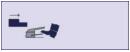
When the padlock is open![]() , it is possible to select and move (Low Speed Down movement) Y1 or Y2 only. This is an easy way to return an unsynchronized beam back to parallel to the table.
, it is possible to select and move (Low Speed Down movement) Y1 or Y2 only. This is an easy way to return an unsynchronized beam back to parallel to the table.
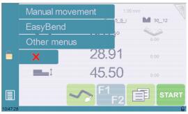
Allows the operator to manually adjust the position of the back gauge (axes X and R) and the beam (axes Y1 and Y2).
This function must be used with utter care and only by experienced personnel. Wrong settings may mechanically damage the machine. Settings are lost after indexing the machine.
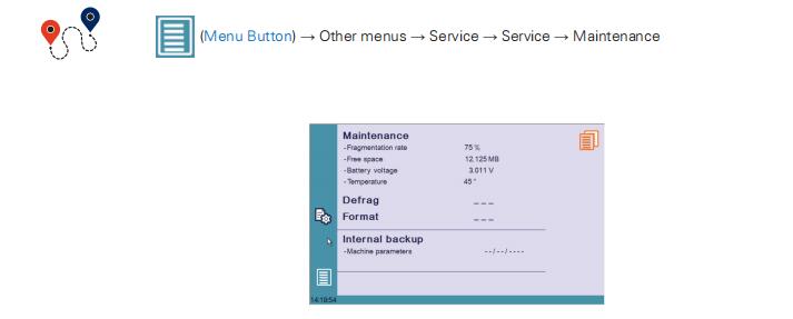
The Maintenance page displays the hardware status of the CybTouch and lets the operator perform different maintenance actions.
This function must be used with utter care and only by experienced personnel. Wrong settings may mechanically damage the machine. Settings are lost after indexing the machine.
This function will rearrange the memory space of the CybTouch. Simply touch it and follow the instructions given in the yellow pop-up window.
This function will erase all data in the CybTouch. Only use this with the help of a technician.
This function is specially designed for OEM and support.
Usually a machine parameters’ backup is made by the machine manufacturer or the company who services the machine. This backup allows a maintenance technician to restore original working parameters if necessary.
Should there be a need to restore parameters, call on a maintenance technician and follow his instructions.
Do not try to use this function unless you are in dire need.
Before using this last function, make sure that all your files have been transfered outside the CybTouch (see USB Transfer, page 16).
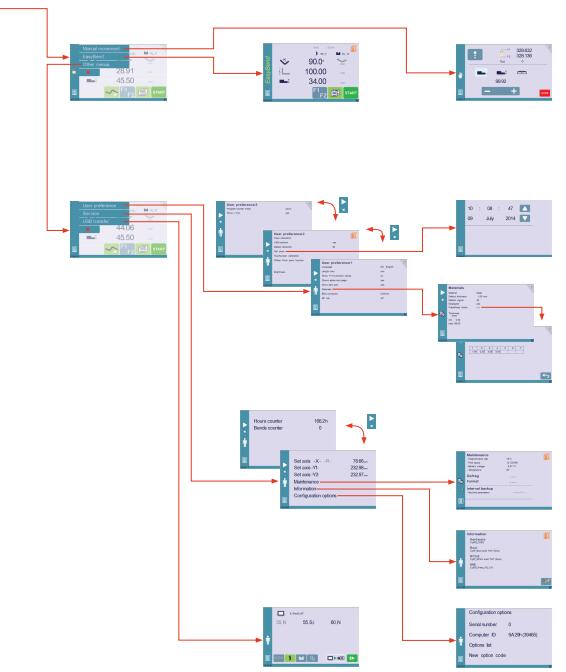
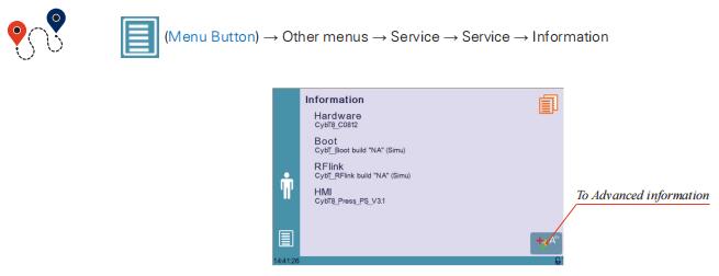
Information The Information page displays the names and versions of the softwares installed on the CybTouch. Pressing the Advanced button shows more detailed information.
Touching this menu opens the following page, where one can find the computer’s identification and manage the machine’s options.
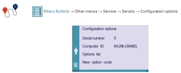
This is the serial number of the CybTouch. It is entered at the factory at the end of the machine’s initial setup and is related to the machine’s option list.
Changing the serial number means that all the options installed on the machine can be lost.
Computer ID
This line displays an identification code that is unique to each CybTouch and guarantees, together with the serial number, a correct identification of the machine.
Option list
This function opens a yellow pop-up window where all the options installed on the CybTouch are displayed.
New option code
The function opens an alphanumerical pad where the code of the new option must be entered. The format of an option code is: ABC-DEF-GHI-JKLM
USB Transfer
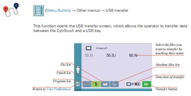
For a smooth transfer, please take the following precautions into consideration:
• The USB port of the CybTouch is meant to be used only with a storage media of the "Memory stick" type.
• The port is a standard USB 2.0 port, USB 1.1 compatible.
• USB 3.0 key that are USB 2.0 compatible, should normally work. There’s however no guarantee, as it depends of the firmware of these new keys.
• CD and external HDD are not accepted.
• Although unlikely, it is possible to find a USB key that is not compatible with the CybTouch. If so, try with another one.
3 rules for a fast and easy transfer:
 Use a USB key dedicated to files transfer with the CybTouch.
 Less files means a faster transfer.
 The file’s path on the key is limited to 255 characters.
CybTouch 8 is delivered with Cybelec’s off-line software PC-ModEva, which controls most of the other numerical controls produced by Cybelec.
From version Tx, PC-ModEva includes CybTouchConverter, which allows you to convert parts to the CybTouch format, and import them into your machine with the above mentioned function.
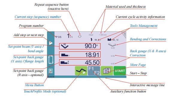
Available functions on the Bend Num page
The Bend Numerical Page is normally the working page, from which the bends are executed, and most of the navigation originates from and leads to.

Set-point beam (Y axis) / bend angle
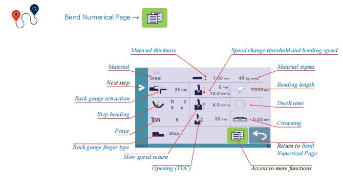
The More page displays parameters related to the part, and depending on the CybTouch configuration and the type of action performed, it also displays various settings for the current bend.


Once activated, this function forces the CybTouch into bottoming mode (see Set-point beam (Y axis) / bend angle, page 18).
With this function, the Speed Change Point occurs higher, and the operator can inch the beam down with short impulses on the pedal, until the proper height is reached. The parameters Speed change threshold and bending speed (see page 20) can also be useful in this situation.
Proceeding this way is normally used for unit or small series. If however the number of parts is large, the operator can enter a target value in the bottoming field, which will then turn black. This way, the CybTouch will execute a normal bending cycle, stopping the beam at the programmed value, i.e. saving a lot of production time.
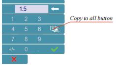
This function allows copying a defined value to all the steps of the current program. It appears in the numerical pad of relevant fields, such as Bending length, Force, Bending and Corrections, etc.
Tools management allows the creation and configuration on the CybTouch of the tools to be used on the machine. These tools are then taken into account in bend calculations.
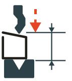
Once a punch and die are created and selected, you can select the bend angle you require as well as the flange length (L). The CybTouch then calculates the positions for axes X and Y for the bend.
Setting Instructions:
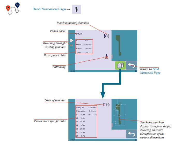
To select a punch, simply browse through the existing punches in your library using the arrows buttons, and then return to Bend Numerical Page.
If no punch is yet created, the punch will have no name (??? is displayed). If a punch already exists, then the last punch used will be selected, here 60_N (modifications will not alter the existing punch as they will be saved under another name).
1. Touch the punch icon ![]() to access the punch details.
to access the punch details.
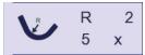
2. Enter the basic characteristics (α (punch angle), Height, Radius and Ton/m) for the new punch to be created.
3. Touch the ![]() button to invert the punch if necessary.
button to invert the punch if necessary.
4. Select the ![]() or
or![]() icon to define the tool as resistant for bottoming.
icon to define the tool as resistant for bottoming.
5. Touch the
![]()
Masters in industrial manufacturing with 25 years of experience and 10+ awards!