Krrass customer support team is here to answer your questions. Ask us anything!
Hi, how can I help?
Preface
This manual describes the operation of the Delem control typeDA-40T and is meant for operators who are instructed foroperation of the total machine.
Limited warranty
1.Introduction
2.Using the DA-40T
2.1 User interface layout
2.2 Available menus
2.3 Key lock
2.4 On screen keyboard
3.Program selectionmode
3.1 Select a program from memory
3.2 Copy/rename/delete a program from memory
3.3 Create a new program
3.4 Column sorting and changing column positions
4.Automaticmode
4.1 Properties
4.2 All steps
4.3 All steps parameters
4.4 Program execution
4.5 Manual positioning
5.Manual mode
5.1 Manual mode parameters
5.2 Program execution
5.3 Manual positioning
6.Settings mode
6.1 General
6.2 Tools
6.2.1 New tool
6.2.2 Copy/rename/delete a tool from memory
6.3 Materials
6.4 Backup / restore
6.5 Program settings
6.6 Time settings
6.7 Maintenance
6.7.1 Setting the calibration point
6.8 System information
7.Diagnostics
7.1 Axis state
7.2 Inputs and outputs
7.3 Signals
1.Introduction
The DA-40T series is a programmable touch control forconventional torsion bar press brake machines.
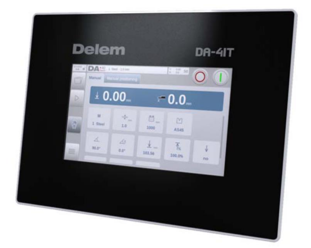
DELEM DA41T Contorl use Hydraulic Press BRAKE
Its user-friendly user interface is mainly based on icons, makingit a fast and easy to program control. The high-qualitywidescreen TFT Color LCD display has a size of 7" and isequipped with an energy saving LED backlight.The industrial grade glass panel with capacitive touchtechnology ensures a safe, reliable and accurate operation,even when wearing gloves in a sheet metal productionenvironment.
2.Using the DA-40T
2.1 User interface layout
The user interface of the DA-40T is based on the proven Delemtouch interface introduced in the Delem press brake controllers.In the picture below the main layout of the screen is explained.This layout is applicable for all the operating modes for the DA-40T, making the navigation easy and recognizable.
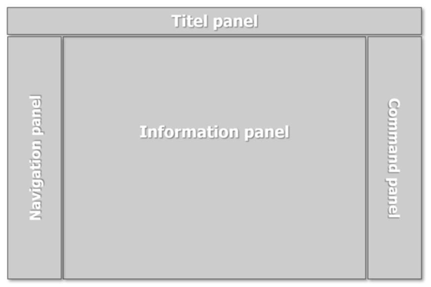
Navigation panel
Title panel
Information panel
Command panel
In order to select a menu item or parameter simply tap thescreen once at the position of the icon. If it is necessary to pan(for example in product select menu), keep your finger on screenand move in the desired direction. Pan is available to scroll inhorizontal as well as vertical direction.
2.2 Available menus
The DA-40T has several modes for programming and operation:
Program selection
Select an existing program, or create a newprogram.

Automatic mode
Execute a program, or program stepparameters.

Manual mode
Execute a single program step.

Settings
Several control settings.

The several modes are explained in detail in chapters 3 to 6.
2.3 Key lock
The control is equipped with a key lock function, to preventunauthorised programming.
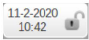
It depends on the machine if this lock is accessible over thetouch screen interface (upper left corner) or an external physicalkey switch.
To lock or unlock the controller, tap the key lock to open the onscreen keyboard. Enter code 42 and press enter. You will seethe status of the key lock is toggled from closed to open or fromopen to closed.
If the control is unlocked (key lock is open), it can beprogrammed as described in this manual. If locked (key lockclosed), the following restrictions apply:
The following actions are still possible when the control islocked:
There is a second code available for the key lock function. Whencode 21 is entered instead of code 42 the user interface is blocked. This can be used to block the machine from unauthorized use without switching the machine off. This special blocked stage can be recognized by an orange colored key lock symbol:
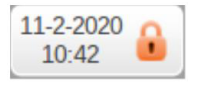
To release the controller for normal operation, tap the key locksymbol and enter code 21 followed by enter.
2.4 On screen keyboard
The DA-40T has a build in on screen keyboard as displayed+below.
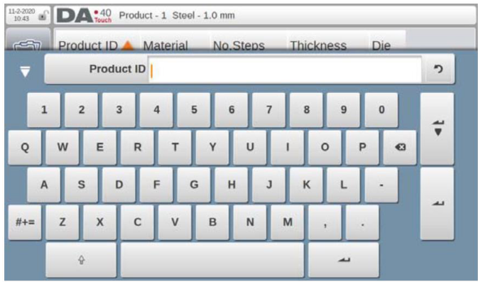
Besides the numerical and alphanumerical keys there are someadditional keys:
Keyboard close
Close the on screen keyboard.

Caps lock
Switch between lower- and upper-casecharacters.

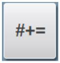
Special characters
Switch the keyboard between normal andspecial characters.
Enter key
This function confirms the entered value,keeps the cursor on the selected inputfield and afterwards automatically closedthe keyboard. This is useful whenentering a single value.

Enter-Next key
This function confirms the entered value,selects the next input field and keeps thekeyboard open. This is useful whenentering multiple values.

Special characters (like á, à, â, ã, ä, å, æ) are also supported.They appear when keeping a character (like 'a') pressed forabout 2 seconds.
3.Programselection mode
By tapping the navigation button Programselection, the control is switched to programselection mode.

3.1 Select a program from memory
To select an existing program from the memory of the DA-40T, simply tap on the program to select it. When the program is successfully loaded the DA-40T will display an informationmessage on the screen that the program is loaded. To executethis selected program, tap on the Automatic mode icon.
3.2 Copy/rename/delete a program from memory
Over the Edit function a selected program can be manipulated:
Copy
Create a copy of the selected program. When making a copy the DA-40T will prompt the keyboard for the user to provide a newname.
Rename
Change the name of the selected program. When renaming theDA-40T will prompt the keyboard for the user to provide a newname.
Delete
Remove the selected program from the memory. When deleting a program from memory the DA-40T will prompt a pop-up to confirm the Delete action. This to prevent an accidental delete action. This action is permanent!
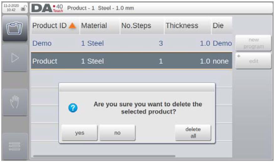
Delete all
Remove all programs from the memory. When deleting all the stored programs the DA-40T will prompt a pop-up to confirm theDelete all action. This to prevent an accidental delete all action.This action is permanent!
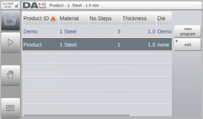
3.3 Create a new program
To create a new program, select the new program soft key. The DA-40T will open the keyboard so the program name can beentered. If an already existing name is entered the DA-40T willprompt a message and asks if the existing program should beoverwritten or not. In case the name was unique the DA-40T willswitch automatically to the automatic mode screen. In automaticmode the several program steps can be defined. See for detailschapter 4.
3.4 Column sorting and changing column positions
Column sorting and changing column width/position areavailable in program selection and automatic mode all stepsscreens.
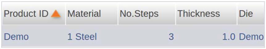
Column sorting
To Sort the data tap shortly in the middle of the column header.To change from ascending to descending tap shortly in themiddle of the column header again. The column that is sorted ismarked with an orange arrow (see the Product header above).
Changing column width
To change the width of a column, tap on the right end of thecolumn header. A box around the column should appear toindicate that column width mode is active. While keeping thescreen pressed move left or right to change the column width.
Changing column position
To change the position of a column, tap in the middle of thecolumn header for 3 seconds. After 3 seconds the column color will invert to indicate that column position mode is active. While keeping the screen pressed move left or right to change the column position.
4.Automaticmode
By tapping the navigation button Automaticmode, the control is switched to Automaticmode.

In Automatic mode a bending program can be defined or editedas explained in chapter 3.
This chapter describes all possible parameters that can be programmed for a program step. Note that most of these parameters are machine configuration dependent; it might be that some of the parameters shown are not present in the userinterface.
Bend programs can only be programmed when tools andmaterials are available, so they must be programmed first. Inorder to execute the programmed product successfully thecalibration point should be set correctly. Refer to paragraph
6.7.1 for setting the calibration point, and paragraph 6.2 for toolprogramming.
4.1 Properties
The ‘Properties’ tab defines the general parameters that applyfor all program steps.
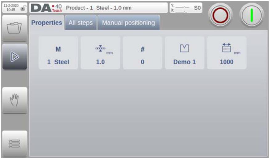
Material number
The material of the sheet. There are 6material types available. Material propertiescan be programmed in Settings mode, asdescribed in paragraph 6.3.

Thickness
The thickness of the sheet.

Product width
This value is used for bending forcecalculation.

Stock counter
To count the number of products. Ifprogrammed to 0, the counter will increaseafter each finished product. If programmedhigher than zero, the counter will countdown. When it has reached 0, the controlwill stop. The stock counter will be reset tothe initally programmed value when ‘start’ ispressed.V0220, 16
![]()
Die ID
The name (ID) of the selected die, which isused for this product.

4.2 All steps
In the ‘All steps’ tab the actual program step parameters are defined. A program consists of a minimum of 1 program stepand a maximum of 25 program steps

Start programming by entering values in the parameter fields. Some parameters are set automatically and can be changed if desired. If there are more parameters available than fits the screen, use the pan function to make the parameters visible. Ifdesired, the order of parameters can be changed, seeparagraph 3.4.
A single step can be inserted or deleted at any point in theprogram.
Insert step
Select the number of the step after which one a step should beinserted (To add a step select the last step in the program).Press the ‘insert step’ soft key; a copy of the selected step willbe inserted. The cursor will automatically move to the new step.
Mark step
Select the number of the step that should be moved or swapped.Press the ‘mark step’ soft key. Then select the next programstep and press the ‘move step’ soft key to move the marked stepto the selected position, or press the ‘swap steps’ soft key toswap the marked step with the selected step
Delete step
Select the number of the step that should be deleted. Press the‘delete step’ soft key; the selected step will be deleted. Thesucceeding steps are shifted up.
A complete program can be deleted in the program selectionmode.
4.3 All steps parameters
Each line represents one step. The first column contains thestep number. For each step, the following parameters can beprogrammed.
Angle
The desired angle value. This parameter isavailable when a tool is programmed.

Angle correction
When angle programming is used, thiscorrection is used to correct Y-axis values.A positive correction means a lower beamposition.

Y-axis bend depth
When an angle is programmed, this valueis calculated. A higher value means a lowerbeam position.

Y-axis opening time
The desired opening time after a bend,programmed as a percentage of themaximum opening time.

Y-axis high speed
To enable high travel speed for the beamduring this bend.

X-axis position
The desired backgauge position for thisbend.

X-axis retract
Backgauge retract distance.
X-axis delay time
Delay time in seconds for X-axis and FDaxis after a step change.

Bending force
The calculated bending force.

Function output
Binary value for the programmable digitaloutputs. The number of available outputsdepends on machine settings. The namealso depends on machine settings, and isFD by default.

4.4 Program execution
When all the program steps have been programmed (or anexisting program is selected) the program can be executed to bend the actual sheet metal parts. To switch to execution mode,press the green start button located in the upper right corner;this can be done on the ‘Properties’ tab or the ‘All steps’ tab.
To start a program, press ‘Start’. The control willbegin execution of the step on which the cursor isplaced.

To stop execution, press ‘Stop’.

When the control is started in ‘All steps’ the screen will look likebelow:
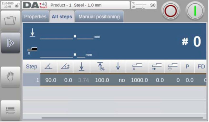
It highlights the active program step, actual Y-axis and X-axispositions and the value of the stock counter.
A program is repeated until 'Stop' is pressed or until the stockcounter (#) has reached 0 after down counting.
A program can only be started when the machine is ready.
4.5 Manual positioning
On the ‘Manual positioning’ page in Manual mode andAutomatic mode a slider at the bottom of the screen can be usedto position the axis.
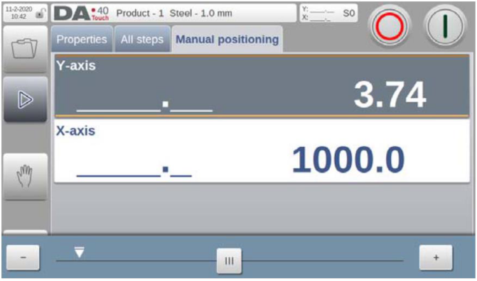
The distance moved with the slider determines the speed of theaxis. When the slider is released, the axis stops. The buttons ateach end of the slider can be used to fine-tune the axis position. When "sliding" the beeper gives feedback that the axis is moving.
5.Manualmode
By tapping the navigation button Manual, thecontrol is switched to Manual mode.

In this mode one bend step can be programmed and executed.
This chapter describes all possible parameters that can beprogrammed for a bend step. Note that most of theseparameters are machine configuration dependent; it might bethat some of the parameters shown are not present in the userinterface.
5.1 Manual mode parameters
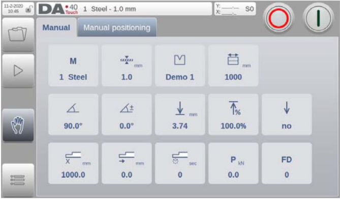
The position of the parameters in the Manual screen can bealtered. To change the position of a parameter, keep its tile pressed until its high-lighted and drag it to the desired position.Release the tile to fix the new position.
Material number
The material of the sheet. There are 6material types available. Material propertiescan be programmed in Settings mode, asdescribed in paragraph 6.3.

Thickness
The thickness of the sheet.

Product width
This value is used for bending forcecalculation.

Die ID
The name (ID) of the selected die, which isused for this product.

Angle
The desired angle value. This parameter isavailable when a tool is programmed.

Angle correction
When angle programming is used, thiscorrection is used to correct Y-axis values.A positive correction means a lower beamposition.
Y-axis bend depth
When an angle is programmed, this valueis calculated. A higher value means a lowerbeam position.
Y-axis opening time
The desired opening time after a bend,programmed as a percentage of themaximum opening time.
Y-axis high speed
To enable high travel speed for the beamduring this bend.
X-axis position
The desired backgauge position.
X-axis retract
Backgauge retract distance.
X-axis delay time
Delay time in seconds for X-axis and FDaxis after a step change

Bending force
The calculated bending force.

Function output
Binary value for the programmable digitaloutputs. The number of available outputsdepends on machine settings. The namealso depends on machine settings, and isFD by default.

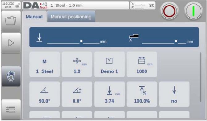
5.2 Program execution
When all the manual mode parameters have been programmedthe single bend can be executed. To switch to execution mode,press the green start button located in the upper right corner.
To start this bend step, press ‘Start’.

To stop execution, press ‘Stop’.

When the control is started the screen will look like below:
5.3 Manual positioning
The manual positioning function of the axis in Manual mode isidentical to the manual positioning in Automatic mode, seeparagraph 4.5.
6.Settingsmode
By tapping the navigation button Settings, thecontrol is switched to Settings mode.

The Settings mode of the control gives access to all kind ofsettings which influence the programming of new products andprograms.
The settings are divided across several tabs logically organizingthe different subjects. In the following sections the available tabsand detailed settings are discussed. Navigation through the tabscan be done by just tapping them and selecting the requireditem to adjust. Since there can be more tabs than the screen canshow in one view, dragging the tabs in horizontal directionenables to view and select all available tabs.
6.1 General
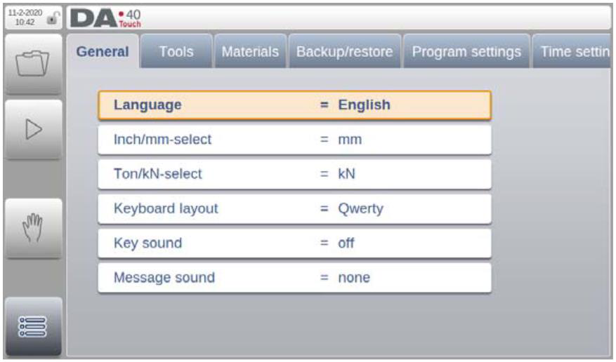
Language
The user interface language can be selected from the list.There are more available languages than initially shown.Scroll vertically by dragging the list up and down to see allavailable languages. Tap to select the desired languagefor the user interface.
Inch/mm-select
Select to use either Millimeters or Inches as the unit to beused.
Ton/kN select
Select to use either Ton or kN as the main unit to be usedfor all force data.
Keyboard layout
Upon choice one can select Qwerty, Qwertz or Azertykeyboard layout. Default layout is Qwerty.
Key sound
Switch the sound function of the input panel on or off.Default sound is on.
Message sound
When the Key sound is off it is still possible to have anacoustic alert in case of a message or warning.• All messages: acoustic alert in case of any message• Errors + Warnings only: acoustic alert only in case of an error or warning
6.2 Tools
On the ‘Tools’ tab the available tools are listed; a new tool canbe created or an existing tool can be edited.
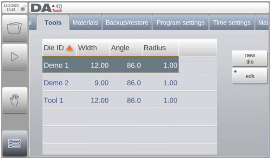
To edit an existing tool simply tab on the tool and the toolproperties window opens. Here the required changes can bemade and confirmed with the accept button.
6.2.1 New tool
To create a new tool press the ‘new die’ soft key. A new dialog is opened where the tool properties can be programmed. These values will be used for automatic bend depth calculation duringbend programming.
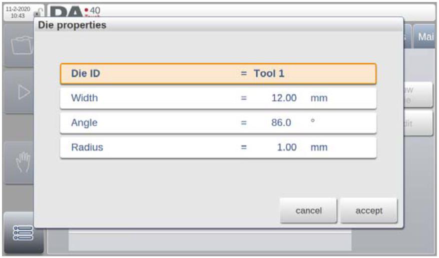
Die ID
A unique name or number to identify the tool. Themaximum length is 25 characters.
Width
The V-opening of the die.
Angle
The angle of the V-opening of the tool.
Radius
The radius of the edges of the V-opening.
6.2.2 Copy/rename/delete a tool from memory
Over the Edit function a selected program can be manipulated:
Copy
Create a copy of the selected tool. When making a copy the DA- 40T will prompt the keyboard for the user to provide a newname.
Rename
Change the name of the selected tool. When renaming the DA-40T will prompt the keyboard for the user to provide a new name.
Delete
Remove the selected tool from the memory. When deleting atool from memory the DA-40T will prompt a pop-up to confirmthe Delete action. This to prevent an accidental delete action.This action is permanent!
Delete all
Remove all tools from the memory. When deleting all the storedtools the DA-40T will prompt a pop-up to confirm the Delete all action. This to prevent an accidental delete all action. This actionis permanent!
6.3 Materials
On the ‘Materials’ tab, 6 different materials with their propertiescan be programmed.
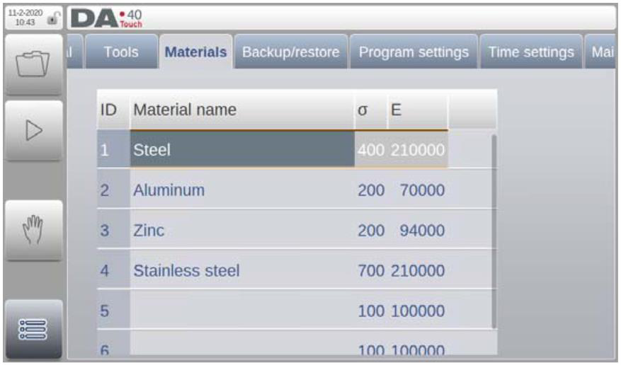
Material name
Name of the material, as it will appear in the programmingscreens. The maximum allowed length of the materialname is 25 characters.
Tensile strength
Tensile strength of the selected material.
E module
E-module of the selected material.
6.4 Backup / restore
The ‘Backup/restore’ tab offers the possibilities to backup and restore products, tools and settings to and from a USB memory device.
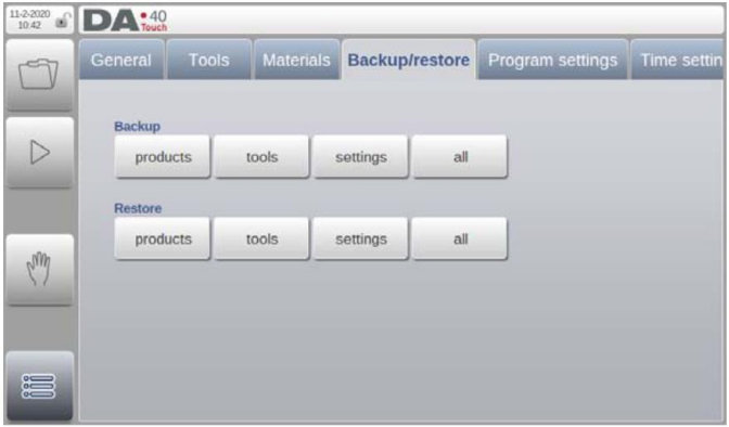
When backup (restore) products, tools, settings or all is selectedfor the first time a new window with a file browser is opened. Inthis window you can browse through the directory structure ofyour backup device. Ta p the directory name on the right part ofthe file browser to look inside a subdirectory. To move one levelup, tap the name on the left part of the file browser.
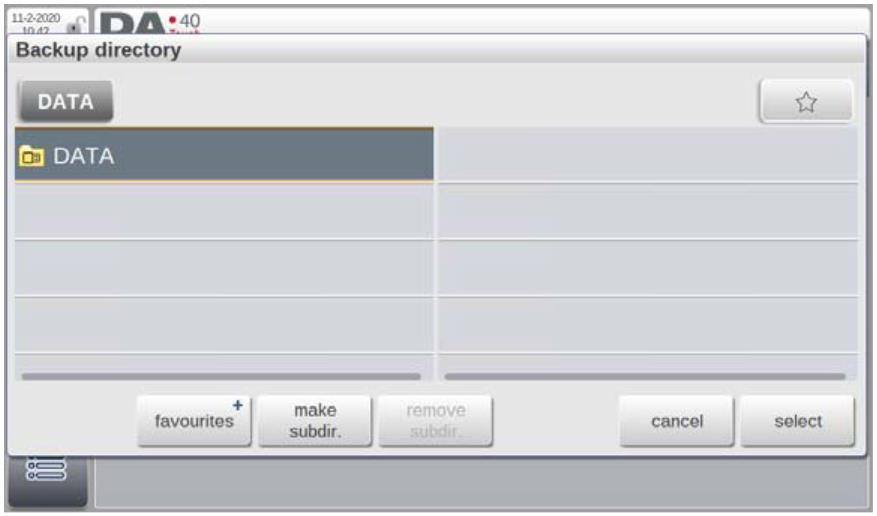
Favourites -> add to favourites
With ‘add to favourites’ it is possible to mark one or more specific directories as favourite. If there are favourite directories
defined a button will be present in the upper rightcorner. By tapping this button, the defined favourites arepresented, making a quick selection of the directory possible.
Favourites -> edit favourites
In this screen the defined favourites can be given a logical name. Next time when opening the favourites by tapping the
button it will be displayed using this logical name.Favourites that are no longer needed can be deleted by tappingthe ‘delete’ soft key.
Make subdir.
Create a new subdirectory
Remove subdir.
Remove an existing subdirectory
Cancel
Exit the file browser screen
Select
Select the directory you are currently in
When the desired backup (restore) directory is selected a newwindow showing all the available products present in thememory is opened.
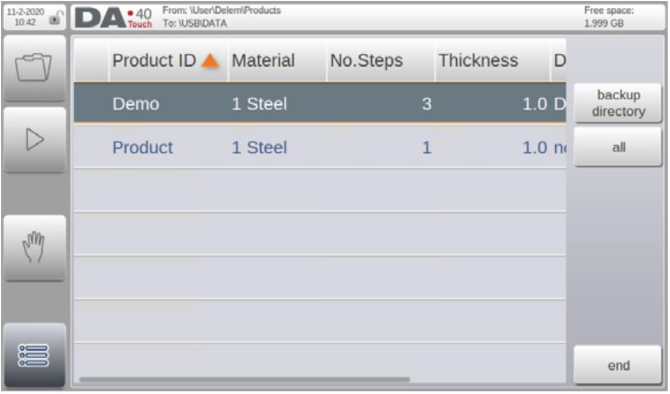
To backup (restore) a single product simply tap on the product tostore it on the back-up device.
To backup (restore) all products choose the ‘all’ soft key.
6.5 Program settings
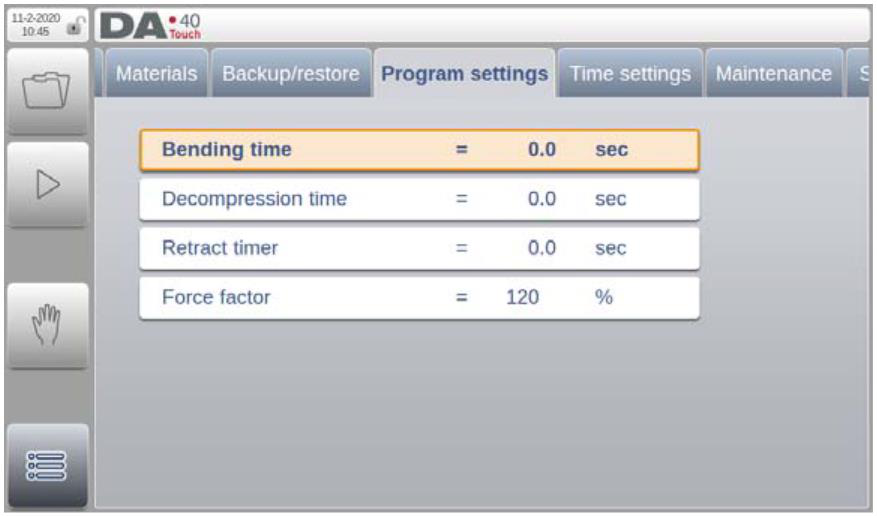
Bending time
The function of this parameter is depending on themachine design. Please contact the machinedocumentation or contact the machine supplier for thefunction of this timer.
Decompression time
The function of this parameter is depending on themachine design. Please contact the machinedocumentation or contact the machine supplier for thefunction of this timer.
Retract time
The moment of X-axis retract is delayed by the valueprogrammed for this parameter.
Force factor
Percentage of calculated force which controls thepressure valve.
6.6 Time settings
In the ‘Time settings’ tab, the date and time as displayed in theupper left corner of the screen can be changed.
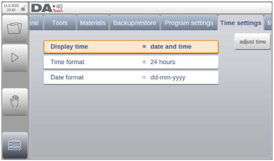
Display time
Display date and time, time only or no time at all on thetitle panel.
Time format
Display the time in 24 hours or 12 hours format.
Date format
Display the date in dd-mm-yyyy, mm-dd-yyyy or yyyy-mm-dd format.
Adjust time
To adjust the date and time. Adjusting the date and time will also adjust the date and time of the operating system.
6.7 Maintenance
On this tab maintenance related functions are located. Next tothe machine hour counter and the machine stroke counter alsofunctions to calibrate the backgauge and to store diagnosticdata can be found here.
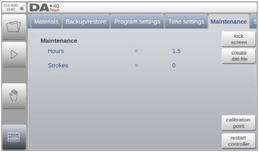
Hours
The number of hours the machine is running.
Strokes
The number of strokes the pressbeam has executed.
Lock screen
To lock the screen, and e.g. clean the screen without changinganything. The screen is unlocked automatically after 5 seconds.
Create .dat-file
Tapping Create .dat-file will store the most important productand control data, by default on the connected USB stick. Thisinformation can be helpful for the maintenance support.
Calibration point
Set the Y-axis calibration point. Refer to paragraph 6.7.1 fordetails.
Restart controller
This will reboot the DA-40T system.
6.7.1 Setting the calibration point
To calibrate the bending depth calculation the calibration pointmust be programmed. This parameter defines the Y-axisposition when the tools are closed. In other words, the Y-axisposition that corresponds with the situation where the lowestpoint of the punch is at the same level as the upper side of theV-die (pinching point with sheet thickness = 0).
This procedure has to be repeated each time the height of the tools that are mounted in the machine have changed.
To set the calibration point, tap on the ‘calibration point’ soft keyon the Maintenance tab in Settings mode.
A practical way to calibrate the machine is to place a sheet ofmaterial with known thickness between the tools and find the Y-axis position at which the punch just touches the sheet (pinchingpoint) using the manual positioning function.
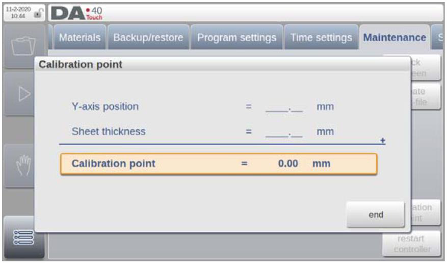
The first parameter indicates the Y-axis position. The second parameter is to define the thickness of the sheet that has been used for the calibration. When the thickness value is entered, the calibration point is calculated automatically.
6.8 System information
On this tab system information can be found. It shows the actualsoftware version; software update functionality is available hereas well.
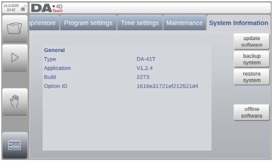
Update software
With ‘update software’ the control can install a software update set from a USB stick. The directory browser will help to selectthe desired update and initiate the installation process.
Backup system
The backup system function makes a complete system backupto a USB stick. A unique time stamped file is written on the USB stick. This backup holds Delem software, OEM specific data as well as the user's files.
Restore system
The restore system function can be used to restore an earliermade backup of the system. During the process selection of what will be restored can be done.
Offline software
The offline software function generates an offline software setup file on a USB stick. This setup can be used to update an existing offline software. Using the matching offline software version withthe control software ensures optimal compatibility of functions.
7.Diagnostics
If the service row is pressed for 2 seconds in Automatic mode orManual mode the DA-40T will enter its built-in diagnostic mode.
The diagnostic mode can be switched off by tapping the servicerow again. These diagnostic screens are intended to be used onrequest of a service engineer from the machine manufacturer.
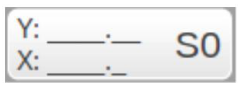
7.1 Axis state
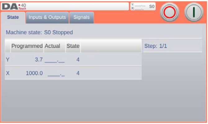
The programmed position, actual position and control state forthe X-axis and Y-axis are displayed.
Mentioned below are the possible machine states:• S0 -> Stopped
7.2 Inputs and outputs
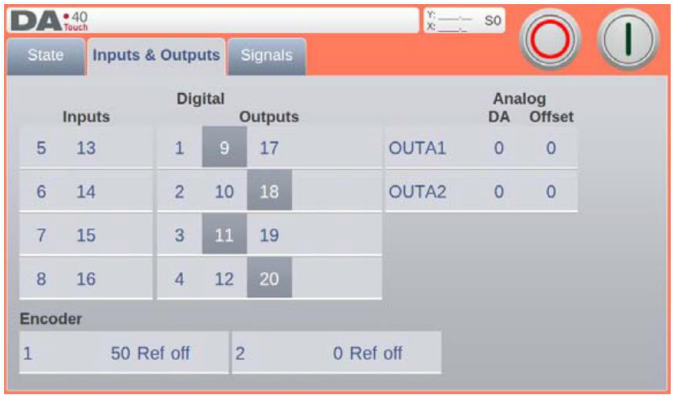
The status of all inputs, outputs and encoders is displayed.
7.3 Signals
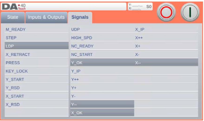
The status of all digital input and output signals is displayed.
![]()
Masters in industrial manufacturing with 25 years of experience and 10+ awards!