Krrass customer support team is here to answer your questions. Ask us anything!
Hi, how can I help?
This manual describes operation of E21 numerical control device and is meant for operators who are instructed for operation of the device. Operator shall read through this manual and know operation requirements before using this device.
Copy right is preserved by ESTUN. It is not allowed to add or delete part or all of the manual content without ESTUN’s consent. Do not use part or all of manual content for the third party’s design.
E21 device provides complete software control and has no mechanical protection device for operator or the tool machine. Therefore, in case of malfunction, machine tool must provide protection device for operator and external part of the machine tool. ESTUN is not responsible for any direct or indirect losses caused by normal or abnormal operation of the device.
ESTUN preserves the right to modifying this manual in the event of function adding or print error.
This product is equipped with press brake machine dedicated numerical control device which is applicable to various users. On the basis of ensuring work precision, the cost of numerical control bending machine is reduced significantly.
Features of this product are listed below:
Positioning control of back gauge.
Intelligent positioning control.
Unilateral and bidirectional positioning which eliminates spindle clearance effectively.
Retract functions.
Automatic reference searching.
One-key parameter backup and restore.
Fast position indexing.
40 programs storage space, each program has 25 steps.
Power-off protection.
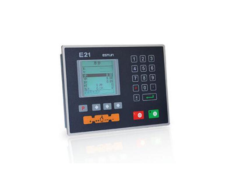
Operation panel is shown in Figure 1-1.
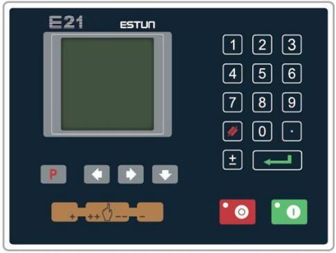
Figure 1-1 Operation panel
Functions of panel keys are described in Table 1-1.
Table 1-1 Description of key functions
| Key | Function description |
| Delete key: delete all data in input area on left bottom of displayer. | |
| Enter key: confirm the input content. If no content is input, the key has the similar function to direction key |
|
| Start key: automatic start-up, top left corner of the key is operation indicator LED. When operation is started, this indicator LED is on. | |
| Stop key: stop operation, top left corner of the key is Stop indicator LED. When initialize normal start-up and no operation, this indicator LED is on. | |
| Left direction key: page forward, cursor remove | |
| Right direction key: page backward, cursor remove | |
| Down direction key: select parameter downward | |
| Function switch: switch over different function pages | |
| Symbolic key: user input symbol, or start diagnosis | |
| Numeric key: when setting parameter, input value | |
| Decimal point key: when set up parameter, input decimal point. | |
| Manual movement key: in case of manual adjustment, make adjustment object move in forward direction at low speed. | |
| Manual movement key: in case of manual adjustment, make adjustment object move in backward direction at low speed | |
| High speed selection key: in case of manual adjustment, press this key and press |
E21 numerical control device adopts 160*160 dot matrix LCD displayer. The display area is shown in Figure 1-2.
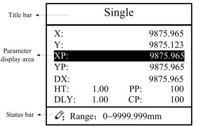
Figure 1-2 Display area
Title bar: display relevant information of current page, such as its name, etc.
Parameter display area: display parameter name, parameter value and system information.
Status bar: display area of input information and prompt message, etc.
The paraphrases of shortening on this page are as shown in Table 1-2.
Table 1-2 The paraphrases of shortening
| Shortening | Description |
| X | The current backgauge position |
| Y | The current slider position |
| XP | The desired backgauge position |
| YP | The desired slider position |
| DX | Backgauge retract distance |
| HT | Holding delay |
| DLY | Retracting delay |
| PP | Preset workpiece |
| CP | Current workpiece |
Basic switch over and operation procedure of the device is shown in Figure 2-1.
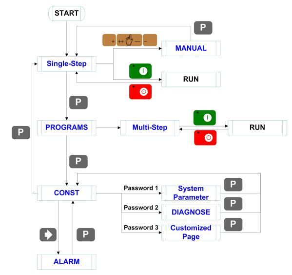
Figure 2-1 Basic Operational Flow
The device has two programming methods, which are single-step programming and multi-step programming. User can set up programming according to actual demand.
2.2.1 Single-step programming
Caution: When the parameter X or Y displays ******** on the page, please do not enter the RUN page or Manual page, unless you have reset the teach function of X-axis or Y-axis.
Single-step programming is generally used for processing single step to finish work piece processing. When controller is power on, it will automatically enter single-step program page.
Operation steps
Step 1 After starting up, the device will enter setting up page of single-step program automatically, as shown in Figure 2-2.
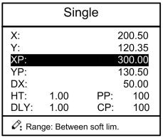
Figure 2-2 Single-step program setting page
Step 2 Press![]() , select parameter which needs to be set up, press
, select parameter which needs to be set up, press ![]() numerical key to input program value, press to complete input.
numerical key to input program value, press to complete input.
[Note] Parameter can only be set when Stop indicator is on.
Setting range of singe step parameter is shown in Table 2-1.
| Parameter name | Unit | Set up range | Remarks |
| X | mm/inch | / | Current position of X axis, unable to be modified. |
| Y | mm/inch | / | Current position of Y axis, unable to be modified. |
| XP | mm/inch | 0~9999.999 | Program position of X axis. |
| YP | mm/inch | 0~9999.999 | Target position of Y axis. |
| DX | mm/inch | 0~9999.999 | Retract distance of X axis. |
| HT | s | 0~99.99 | The time between concession signal valid and end hold time output. |
| DLY | s | 0~99.99 | In case of single step, delay time for X axis concession. |
| PP | / | 0~99.99 | Number of preset work piece |
| CP | / | 0~99.99 | Number of current work piece. |
Step 3 Press ![]() , system will execute according to this program, as shown in Figure 2-3.
, system will execute according to this program, as shown in Figure 2-3.
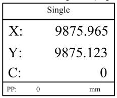
Figure 2-3 Single step operation page
On single-step program page, program bending depth to 100.0mm, back gauge position to
80.00mm, retract distance to 50mm, concession waiting time to 2s, holding time to 3s, work
piece to 10.
Operation steps are shown in Table 2-2.
Table 2-2 Operation steps of single step example
| Operation steps | Operation |
| Step1 | Press |
| Step2 | Input 80.00 by numerical key. |
| Step3 | Press |
| Step4 | Press |
| Step5 | Input 100.0 by numerical key. |
| Step6 | Press |
| Step9 | Press parameter, “HT” parameter, “PP” parameter respectively. |
| Step10 | Set up parameter to 50mm, 2s, 3s, 10, 0 by numerical key. |
| Step11 | Press |
2.2.2 Multi-step programming
Caution: When the parameter X or Y displays ******** on the page, please do not enter the RUN page, unless you have reset the teach function of X-axis or Y-axis.
Multi-step program is used for processing single work piece of different processing steps, realize consecutive implementation of multi-steps, and improve processing efficiency.
Operation step
Step 1 Power on, the device displays the single-step parameter page automatically.
Step 2 Press ![]() , switch to program manage page, as shown in Figure 2-4.
, switch to program manage page, as shown in Figure 2-4.
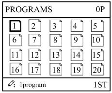
Figure 2-4 Program management page
Step 3 Press ![]()
![]()
![]() , select program serial number, or input program number directly, such as input “1”.
, select program serial number, or input program number directly, such as input “1”.
Step 4 Press ![]() , enter multi-step program setting page, as shown in Figure 2-5.
, enter multi-step program setting page, as shown in Figure 2-5.
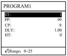
Figure 2-5 Multi-step
Step 5 Press ![]() , select multi-step programming parameter which requires set up, input
, select multi-step programming parameter which requires set up, input
setting up value, press ![]() , and the set up takes effect.
, and the set up takes effect.
Step 6 In completion of set up, press ![]() , enter step parameter set page, as shown in Figure 2-6.
, enter step parameter set page, as shown in Figure 2-6.
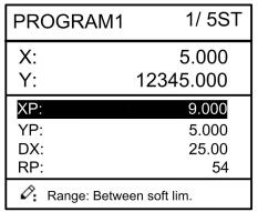
Figure 2-6 Step parameter set page
Step 7 Press ![]() , select step parameter that needs to be set up, input program value, press
, select step parameter that needs to be set up, input program value, press ![]() , and the setup takes effect.
, and the setup takes effect.
Step 8 Press ![]()
![]() to switch over between steps. If the current step is the first step, press
to switch over between steps. If the current step is the first step, press ![]() to enter the last page of step parameter setting; if the current step is the last one, press
to enter the last page of step parameter setting; if the current step is the last one, press ![]() to enter the first page of step parameter setting.
to enter the first page of step parameter setting.
Multi-step parameter setting range is shown in Table 2-3.
Table 2-3 Multi-step parameter setting range
| Parameter name | Unit | Setting range | Remarks |
| Step number of program | / | 0~25 | Set up total processing step number of this program |
| Preset work piece number | / | 0~9999 | Number of work piece to be processed, decreasing piece when more than zero; negative increasing count. |
| Current work piece number | / | 0~9999 | Number of finished work piece |
| Concession delay | s | 0~99.99 | Time between retract signal and concession execution. |
| Holding time delay | s | 0~99.99 | Time between concession signal and end pressurize output |
| X | mm/inch | / | Current position of X axis, can’t be modified; |
| Y | mm/inch | / | Current position of Y axis, can’t be modified; |
| X target position | mm/inch | / | Program position of X axis; |
| Y target position | mm/inch | / | Target position of Y axis; |
| concession distance | mm/inch | 0~9999.999 | Distance of X axis concession; |
| Repeat times | / | 1~99 | Repeat times required by this step. |
Step 9 Press ![]() , system will operate according to this program, as shown in Figure 2-7.
, system will operate according to this program, as shown in Figure 2-7.
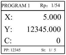
Figure 2-7 Multi-step programming operation page
[Background] One work piece requires processing 50 as shown below;
First bend: 50mm;
Second bend: 100mm;
Third bend: the other direction 300mm;
[Analysis] according to work piece and technological conditions of machine tool:
First bend: X axis position is 50.0mm; Y axis position is 85.00mm, concession 50mm;
The second bend: X axis position is 100.0mm; Y axis position is 85.00mm, concession 50mm;
The third bend: X axis position is 300.0mm; Y axis position is 85.00mm, concession 50mm;
Edit processing program of this work piece on No. 2 program.
Operation procedure is shown in Table 2-4.
Table 2-4 Operation steps of multi-step programming example
| No. | Operation |
| Step1 | On single step parameter setting page, press |
| Step2 | Input “2”, press program 2. |
| Step3 | Select “Program step”, input “3”, press |
| Step4 | Select “number of preset work piece”, input “50”, press takes effect. |
| Step5 | Similar to step 3 and step 4, set “current work piece number”, “concession delay” and “pressurize time” to 0, 400, 200 respectively. |
| Step6 | Press |
| Step7 | Select “X target position”, input 50, press |
| Step8 | Select “Y target position”, input 85, press |
| Step9 | Similar to step 7, 8, set up “concession distance” and “repeat times” to 50, 1 respectively. |
| Step10 | Press method is similar to that of step one. |
| Step11 | Press |
<Note>
■ In completion of multi-step programming, return to start step before launching the system; otherwise, the program will start position processing at current step.
■ Press left and right direction key to circulate page turning and browsing among all step parameters.
■ Program can be called and revised again.
■In completion of processing all work pieces (50 in the example), system stops automatically. Restart directly will start another round of processing 50 work pieces.
User can setup all parameters required for normal operation of the system, including system parameter, X axis parameter and Y axis parameter.
Step 1 On program management page, press ![]() to enter programming constant page, as shown in Figure 2-8. On this page, programming constant can be set.
to enter programming constant page, as shown in Figure 2-8. On this page, programming constant can be set.
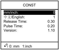
Figure 2-8 Programming constant page
Range of programming constant setup is shown in Table 2-5.
Table 2-5 Range of programming constant setup
| Parameter name | Unit | Range | Default | Remarks |
| mm/inch | / | 0 or 1 | 0 | 0: mm, 1: inch |
| 中文/English | / | 0 or 1 | 0 | 0: Chinese, 1: English |
| Release Time | s | 0 to 99.99 | 0.3 | Continue time of unloading output after starting the system. |
| Pulse Time | s | Time s 0.000 to 1.000 | 0.2 | The duration of the pulse signal. |
| Version | / | / | / | Software version information, V refers to version. 1: indicates version number. 0: indicates version level. |
Step 2 Input password “1212”, press ![]() to enter the Teach Page, as shown in Figure 2-9.
to enter the Teach Page, as shown in Figure 2-9.
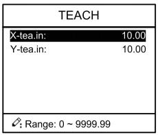
Figure 2-9 System parameter setting page
Step up parameter, parameter setup range is shown in Table 2-6.
Table 2-6 System parameter setup range
| Parameter name | Unit | Range | Default | Remarks |
| X-tea.in | mm | 0~9999.99 | 10 | In teach enable, input current position of X axis |
| Y-tea.in | mm | 0~9999.99 | 10 | In teach enable, input current position of Y axis |
<How to Teach>: You can directly measure the positions of slider and back gauge. If the measurement is difficult, you can program and operate any one process, and then measure the accomplished workpiece.
Step 3 Press ![]() , return to programming constant page.
, return to programming constant page.
----End
In single-step mode, axis movement can be controlled by pressing key manually. This method helps user to adjust machine tool and work piece.
Step 1 On single step parameter setup page, press ![]() or
or ![]() to enter manual page, as shown in Figure 2-10.
to enter manual page, as shown in Figure 2-10.
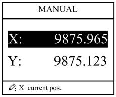
Figure 2-10 Manual page
Step 2 According to your actual requirement, following the above table to adjust the position of the axis. - If the drive mode of the corresponding axis is common motor:
| Press Key | Status | Direction | Running Time | Speed |
| Stop | increasing | Press time | Slow | |
| Run | increasing | Press time (if it is less than “Pulse Time”) Pulse Time (If it is less than Press time) |
Slow | |
| Stop | decreasing | Press time | Slow | |
| Run | decreasing | Press time (if it is less than “Pulse Time”) Pulse Time (If it is less than Press time) |
Slow | |
| Stop | increasing | Press time | Slow | |
| Run | increasing | Press time | Slow | |
| Stop | decreasing | Press time | Slow | |
| Run | decreasing | Press time | Slow |
<Note>: When the system is on run status, the operation of manual adjustment is just valid for the X-axis.
- If the drive mode of the corresponding axis is frequency:
| Press Key | Status | Direction | Running Time | Speed |
| Stop | increasing | Press time | Slow | |
| Run | / | |||
| Stop | decreasing | Press time | Slow | |
| Run | / | |||
| Stop | increasing | Press time | Fast | |
| Run | / | |||
| Stop | decreasing | Press time | Fast | |
| Run | / | |||
Step 3 Press ![]() return to single step parameter setting page.
return to single step parameter setting page.
----End
The device can detect internal or external abnormity automatically and send out alarm prompt. Alarm message is available on alarm list.
Step 1 On programming management page, press ![]() to enter programming constant page.
to enter programming constant page.
Step 2 On programming constant page, press ![]() to enter “Alarm history” page to view all alarm history.
to enter “Alarm history” page to view all alarm history.
As shown in Figure 3-1, the latest 6 alarms, alarm number and causes can be viewed on this page
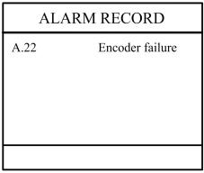
Figure 3-1 Alarm history page
Alarm history and message is shown in Table 3-1.
Table 3-1 Alarm number and alarm message
| Alarm number | Alarm name | Alarm description |
| A.02 | XPos < minimum | Move X-axis forwards in Manual Movement. |
| A.03 | XPos > maximum | Move X-axis backwards in Manual Movement. |
| A.04 | YPos < minimum | Move Y-axis forwards in Manual Movement. |
| A.05 | YPos > maximum | Move Y-axis backwards in Manual Movement. |
| A.06 | X out of lmt. | Re-teach the position of X-axis. |
| A.11 | Count reached shut-down | Rerun, the alarm is cleared automatically. |
| A.12 | Beam is not on upper dead point | Step on the Foot Up Switch, moving the slider to the TDC, and the alarm will be cleared automatically. |
| A.13 | X Un-teachIn | Re-teach the position of X-axis. |
| A.14 | Y Un-teachIn | Re-teach the position of Y-axis. |
| A.21 | Oil pump not started | Check whether the pump signal is connected, and check whether the pump switch is on. |
| A.22 | Encoder failure | Check whether the encoder wiring is normal. |
| A.25 | Drive mode err | Reprogram the Drive Mode for X-axis and Y-axis. |
| A.26 | X Stop Err | Check whether the back gauge motor is run normally |
| A.27 | Y Stop Err | Check whether the slider motor is run normally. |
| A.28 | X V2 Err | Check whether the back gauge motor is run normally. |
| A.29 | X V3 Err | Check whether the back gauge motor is run normally. |
| A.30 | Y V2 Err | Check whether the slider motor is run normally. |
| A.31 | Y V3 Err | Check whether the slider motor is run normally. |
| A.32 | XPos < 0 | Move X-axis forwards to the setting range in Manual Movement. |
| A.33 | YPos < 0 | Move Y-axis forwards to the setting range in Manual Movement. |
| A.41 | Parameter storage error | Back to factory for repairing |
| Fault phenomena | Trouble shooting |
| The screen don’t display when power on. |
The terminal of power supply wiring is error. Follow the nameplate to rewire. The source voltage is too low. The connector is not connected well. |
| The back gauge motor doesn’t run when X-axis is operated, but the slider motor runs |
The wires of these two motor are in reverse, please rewire. |
| The motor doesn’t run when operating. |
Check whether the machine is impeded, or whether the slider is back to TDC Check whether the motor wire is connected well. |
| The motor can’t mutually convert from high to low |
Check whether the signal is in effect, or whether frequency converter is normal. Check whether parameter Mute Dis. is programmed correctly. |
| The step can’t be changed in Multi-Step mode. |
Check the START terminal is connected to +24V when the slider is on TDC. |
| The counter doesn’t work in Multi-Step mode. |
Check the START terminal is connected to +24V when the slider is on TDC. |
| Lose control of the system | Check whether the encoder cable is connected well. Check whether the motor direction wiring (X+, X-, Y+, Y-) is correct. |
| The actual position of X-axis or Y-axis is unchanged or unshown. | Check whether the encoder cable is connected well or correctly. |
---End
![]()
Masters in industrial manufacturing with 25 years of experience and 10+ awards!