Krrass customer support team is here to answer your questions. Ask us anything!
Hi, how can I help?
Purpose
This document provides guides to use the E300 device for the jobs.
According to this document, you can learn how to program the product by the E300 device.
Audience
This document is intended for:
Technical support engineer
Installation and Commissioning engineer
operating staff
Organization
| Chapter | Content |
| Chapter 1 Outline | This chapter describes the features, appearance, and electrical specification of the E300 device. |
| Chapter 2 Programming | This chapter guides the user how to program the product by the E300 device. |
| Chapter 3 Basic Operation | This chapter describes the basic operation of the E300 device. |
Conventions
The symbols that may be found in this document are defined as follows.
| Symbol | Description |
 |
WARNING Indicates a potentially hazardous situation which, if not avoided, couldresult in death or serious injury to personnel. |
 |
CAUTION Indicates a potentially hazardous situation which, if not avoided, couldresult in minor or moderate injury to personnel and damage to equipment. It may also be used to alert against unsafe practices. |
 |
MANDATORY Always be sure to follow explicitly the items listed under this heading. |
 |
PROHIBITED Must never be performed. |
 |
NOTE or TIP Provides additional information to emphasize or supplement important points of the main text. |
| Convention | Description |
| Times New Roman | Normal paragraphs are in Times New Roman. |
| Boldface | Names of files, directories, folders, and users are in boldface. For example, log in as user root |
| Courier New | Terminal display is in Courier New. |
| Italic | Book titles are in italics. |
| Format | Description |
| Boldface | Buttons, menus, parameters, tabs, windows, and dialog titles are in boldface. For example, click OK. |
| XX>XX | Multi-level menus are in boldface and separated by the ">" signs. For example, choose File>Create>Folder. |
| Format | Description |
| Key | Press the key. For example, press Enter and press Tab |
| Key 1+Key 2 | Press the keys concurrently. For example, pressing Ctrl+Alt+A means the three keys should be pressed concurrently. |
| Key 1, Key 2 | Press the keys in turn. For example, pressing Alt, A means the two keys should be pressed in turn. |
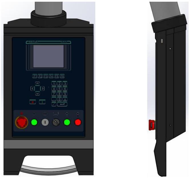
Figure 1-1 The suspension cabinet
The E300 device inherits ESTUN classic mode of operation, through a simple and intuitive parameter configuration interface to complete the bending machine control operation. Its friendly
interface, easy to use, practical function, and has the following features:
4 axes are supported, viz, X-axis, Y-axis, R-axis and C-axis.
Automatic calculation of the block position, according to the bending angle, material, thickness and mold parameters.
The back gauge can be controlled in a high-accuracysince the servo systems control X-axis and R-axis.
Optional hydraulic or mechanical to control the C-axis.
Program in absolute value or angle.
You can backup, restore, import and export the parameters, for commissioning the machine easily.
Edit the program in one page, for improving the operating efficiency.
You can program the dwell time (holding time) andretracting delay by the device instead of the time relay.
Interference or collision of the die can be avoided.
The opening distance can be adjusted, for improving the operating efficiency.
Automatically adjust the clamping point position.
You can view the status of inputs, outputs, valves and faults on the Monitor page at any time.
Automatically adjust the zero position of the R-axis.
Materials and die informations are programable.
Three of operation mode (Jog, Single, Continuous) for the jobs.
Language setting and unit setting.
IO ports can be allocated freely, and the device can detect them for avoid the repeat.
Bilateral positioning and unilateral positioning.
Slug clearance function.
Teaching or search the reference point.
The Axis, which is controlled by a servo system, can be manually moved.
Real-time memory the parameters, positions and programs against the unexpectedaccidents such as interruption of power supply.
Figure 1-2 is the appearance of the suspended device, and it includes many elements.
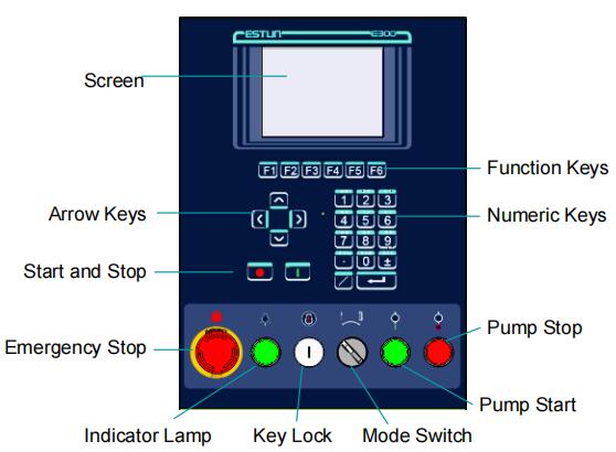
Figure 1-2 Appearance of the suspended device
Table 1-1 lists the description of each element.
Table 1-1 Description of each element
| Element | Description |
| Screen | 5.6 inch, 640 × 480 dot matrix, 18-bit full color display screen. |
| Function Keys | Function keys, which corresponding to options on below of each page. |
| Numeric Keys | It consists of CLEAR, NUMBERS, POINT, ± and ENTER. They are often used in programming and settings. |
| Arrow Keys | Press these buttons can move the cursor. |
| Start and Stop | Press START key when your program has been completed, and each axis can perform the positioning. Press STOP key, the machine can stop running. |
| Mode Switch | Turn this switch for switching the operation mode between Single and Jog. <NOTE>: For switching the operation mode to Continuous mode, turn the switch to Single mode, and set the parameter Automatic to Enable on the HMI. |
| Emergency Stop | In the case of emergency stop use the EMERGENCY STOP controller |
| Key Lock | A key lock, which can turn ON or turn OFF the device. |
| Indicator Lamp | When the device is power on, the indicator lamp can be lighted |
| Pump Start | Press this button can turn on the oil pump, indicating the machine is ready |
| Pump Stop | Press this button can turn off the oil pump, indicating the machine is unable to run. In addition, this signal can be cut off when EMERGENCY STOP button was pressed down. |
There are 6 kinds of ports on the E300 device, which can connect the external devices. Table 1-2lists the description of them.
Table 1-2 The description of Ports
| Port | Diagram | Amount | Description |
| USB | / | 1 | Connect a U disk, which can help the USB - 1 user by performingmany operations such as update, import or export the parameters, dies and programs. |
| DB-9 (Male) |
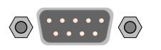 |
1 | Reserved. |
| IO | 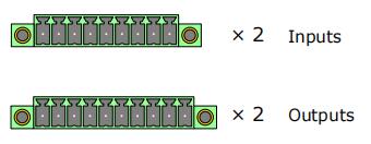 |
4 | 2 groups of inputs, each group have 9 pins. 2 groups of outputs, each group have 10 pins. |
| RJ45 |  |
1 | Connect the servo system by CAN protocol. |
| DB-15 (Female) |
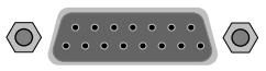 |
1 | Connect the external device, which controls C-axis. |
| DB-9 (Female) |
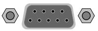 |
2 | Reserved. |
| Power Supply | |||
| Item | Voltage | Rated Current | Starting Current |
| Minimum | 20 | 1.2 | / |
| Standard | 24 | 2 | / |
| Maximum | 28.8 | 3 | 3 |
| Unit | V | A | A |
| Inputs | |||
| Input Voltage | 24VDC±10% | ||
| Input Current | 5mA | ||
| Signal Characteristic | H-level is not greater than 30V L-level is not greater than 1.2V |
||
| Effective Level | H-level | ||
| Outputs | |||
| Output structure | Open Collector | ||
| Output Voltage | Not greater than 30VDC | ||
| Output Current | Not greater than 150mA | ||
| Signal Characteristic | H-level is not greater than 30V L-level is not greater than 1.0V |
||
| Effective Level | L-level | ||
| Encoder | |||
| Supported Type | Differential / Line Driver | Complementally / Voltage | |
| Supply Voltage | 5V DC | 12V DC | |
| Supply Current | 500mA | ||
| Response Frequency | 500KHz | ||
| Input Phases | A, B, C, A\, B\, C\ | ||
| Output Phases | A, A\, B, B\, C, C\ | A, B, C | |
| Output Voltage | H-level is not less than 80%VCC L-level is not greater than 0.3V |
||
| Communication | ||||
| Protocol | CAN | RS485 | RS232 | |
| Transmission Rate | 1 Mbps | 10 Mbps | 115.2 Kbps | |
| Terminal Resistance | Build-in | None | ||
| ESD | 16KV HBM | 15KV HBM | ||
| Analog Input | ||||
| Type | Voltage | |||
| Range | From ﹣10V to ﹢10V | |||
| Resolution | 12bit | |||
| Channels | 3 channels | |||
| Sampling Frequency | Not greater than 78KHz | |||
| Analog Output | ||||
| Type | Voltage | |||
| Range | From ﹣10V to ﹢10V | |||
| Resolution | 12bit | |||
| Channels | 2 channels (AO1 to AO4) | |||
| Environment | ||||
| Operating TMP | 0℃ to 40℃ | |||
| Operating Humidity | 5% to 95%, no condensation | |||
| Storage TMP | ﹣20℃ to 70℃ | |||
| Storage Humidity | 5% to 95%, no condensation | |||
Power up the device and wait for a while, the screen can display the initialpage (Single-Step) automatically, as shown in Figure 2-1
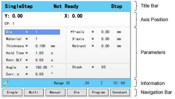
Figure 2-1 The initial page
This area is displayed on every page, and from left to right are Page Name, System Status, and Operation Mode in turn.
Page Name: displayed the current page’s name, e.g. SIngleStep, Multi, Program.
System Status: displayed the current system status. There are six system statuses, as shown in Table 2-1.
Table 2-1 The description of the system status
| System Status | Description |
| Not Ready | When power up the device, the system detects the signalPump is turned OFF, this system status is displayed. |
| Idle | When this system status is displayed, the signal Pump is turned ON, and the signal RDY is also turned ON. Only under this system status, the machine can run the programming after you has completed the program and press down the START key. |
| Run | When the system is working, this status is displayed. When you press STOP key on the operation panel, the machine stops and the system status is switched to Idle. If the Count Mode is set to Cnt Down, when the counting has been finished,(Stock is 0), the machine stops and the system status is switched to Idle. When any problem doesn’t meet the device settings or prevents normal operation is detected,the machines stops and the system status is switched to Alarm. |
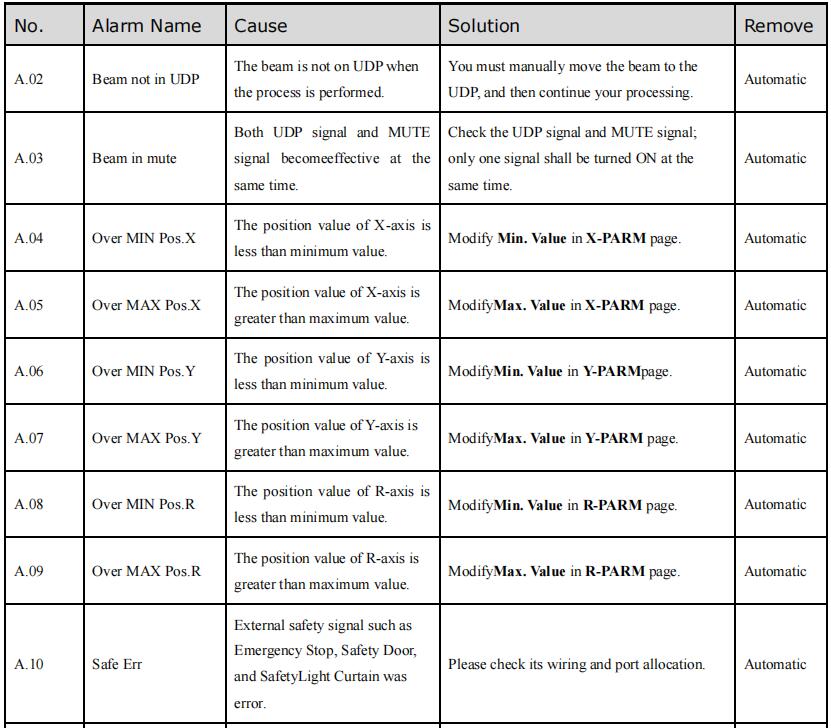
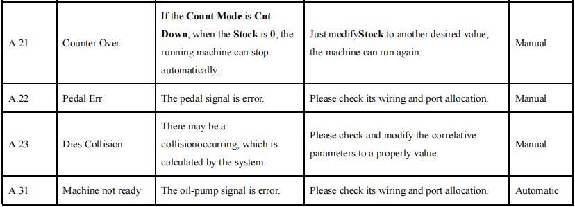
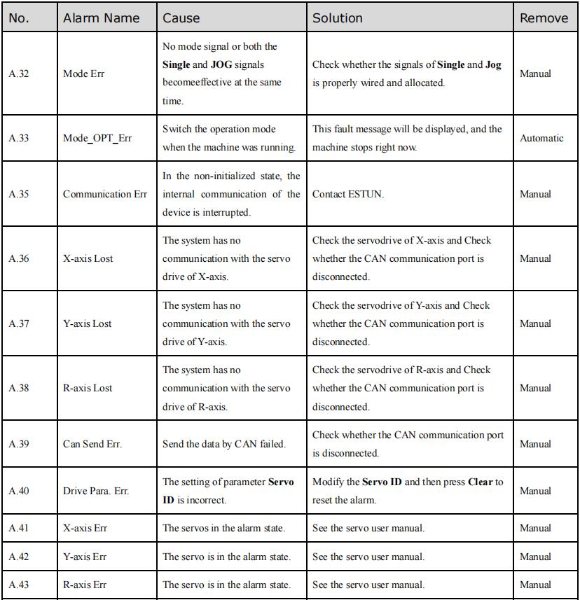
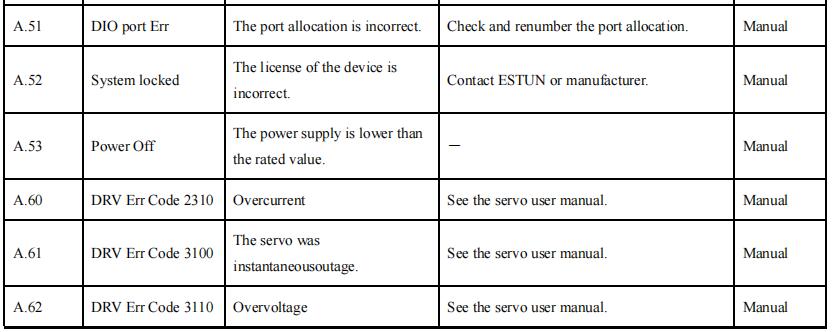
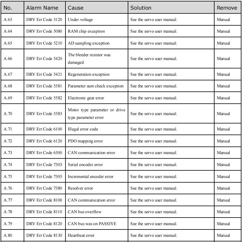
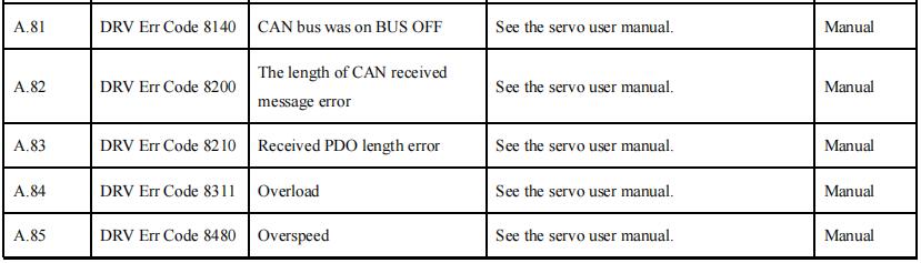
| Alarm | When any problem doesn’t meet the device settings or prevents normal operation is detected, the status is displayed. Follow the section Appendix D Alarm List, solving the fault according to the fault message, and then move the cursor on Clear, and press ENTER key, so that the system can try to reset. |
Operation Mode: displayed the current operation mode. There are three operation modes, as shown in Table 2-2.
Table 2-2 The description of the operation mode
| Operation Mode | Description |
| Single | Switch the operation mode to Single, and the parameter Automatic to Disable, this operation mode is displayed on the page. In this operation mode, you shall change step by stepping on the foot switch (Pedal Signal) when the previous step has been finished. |
| JOG | When this system status is displayed, the signal Pump is turned ON, and the signal RDY is also turned ON. Only under this system status, the machine can run the programming after you has completed the program and press down the START key. |
| Continue | Switch the operation mode to Single, and the parameter Automatic to Enable, this operation mode is displayed on the page. In this operation mode, the system can change step automatically when the previous step has been finished. |
This area displays the current position value of the axes.
Note: In general, the default issued E300 device is the standard version, which only supports the control of X-axis and Y-axis. For the more features, you can contact ESTUN.
This area displays the parameters information. Each page has corresponding parameters, for details about the parameters see the description of the other sections in this manual.
This area displays the information of each parameter, including editing value and range. The right side of this area is the system time.
This area displayed each main page you may be switched, corresponding to the F1 to F6 keys on the operation panel.
Table 2-3lists the descriptions of each main page.
Table 2-3 The descriptions of each main page
| Key | Page | Description |
| F1 | Single | This page is used for setting the parameters of the single-step programming. Single-step programming is commonly employed for quick bending. |
| F2 | Multi | This page is used for setting the parameters of the Multi-step programming. Multi-step programming is commonly employed for the complex bending, which consist of many different bending steps. |
| F3 | Manual | The servo axes, which are controlled by servo motor, can be moved manually with the arrow keys in this page. You can perform this operation without starting the device. |
| F4 | Die | This page lists the information of the set and stored dies. |
| F5 | Programe | This page lists the information of the set and stored programs. |
| F6 | Constant | The commonly used parameters are displayed on Constant page. |
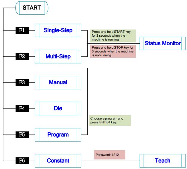
Figure 2-2 Operation flow diagram
You can program the bending steps for the same settings on this page, which is commonly employed for quick bending.
This page is the initial page when you power up the device. Press F1 key to enter the Single-Step page, as shown in Figure 2-3.
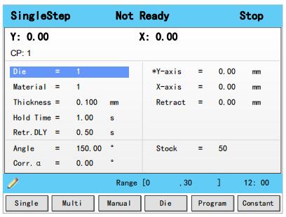
Figure 2-3 The Single-Step page
Table 2-4 lists the description of the parameter on this page. You can refer to this table when you edit the parameters on this page.
Table 2-4 The description of the parameter on Single-Step page
| Parameter | Description |
| Die | Default 1 Range 0 to 30 Unit -Description Set a desired die ID for the program. The parameters of the die can be edited on Die page. |
| Material | Default 1 Range 1 to 6 Unit -Description Set a desired material ID for the program, which is used for calculating the bending depth. The parameters of the material can be edited on Material Table page. |
| Thickness | Default 0 Range 0.000 to 99.999 Unit mm Description The thickness of the sheet. |
| Hold Time | Default 0 Range 0.00 to 99.99 Unit s Description The hold (dwell) timeof punch at the bending point |
| Retr.DLY | Default 0 Range 0.00 to 99.99 Unit s Description The wait time before the X-axis performs the retract. |
| Angle | Default 0 Range 0.00 to 180.00 Unit ° Description Set a desired angle value in the selected bending step. |
| Corr.α | Default 0 Range -90.00 to 90.00 Unit ° Description This parameter is valid when the bending method is angle, which indicates the correction on angle to the current bending step . For example: If the programmed value is 90, while the actual measured value is 92, then this parameter shall be set to -2. If the programmed value is 90, while the actual measured value is 88, then this parameter shall be set to 2. |
| Y-axis | Default 0 Range 0.000 to 9 999.999 Unit mm Description The programmed value for the Y-axis. |
| X-axis | Default 0 Range 0.000 to 9 999.999 Unit mm Description The programmed value for the X-axis. |
| Retract | Default 0 Range 0.000 to 9 999.999 Unit mm Description Retract distance of the selected axis in the current bend. The "backgauge retract" is started when the beam is pinching the sheet. |
| Open | Default 0 Range 0.00 to 99.99 or 0.000 to 9 999.999 Unit s or mm Description Set the opening distance or opening time for the opening process. |
| Stock | Default 0 Range -1 to 999 999 Unit - Description The stock counter is incremented or decremented after each end of a program cycle, which depends on the settings of the parameter Count Mode. Set it to -1, indicating the stock count is disabled. Set it to other value: When the Count Mode is Cnt Down, the stock counter in production mode is decreased by 1 after each product cycle. When the counter has reached 0, the machine is stopped. When the Count Mode is Cnt Up, the stock counter in production mode is increased by 1 after each product cycle. |
We take the following process as an example to describe the programming.
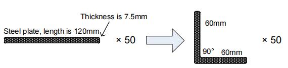
Steel plate, length is 120mm 60mm 90° 60mm Thickness is 7.5mm × 50 × 50.
In this example, we can learn a set of the basic data: material is steel; X-axis is 60; bending-angle is 90; thickness is 7.5; stock is 50.
We decide to program the process by the given angle, and supposing the die ID is 1.
In addition, we can set some other necessary parameters according to our experience, such as holding time is 3, retracting delay is 2, and retract distance is 5.
Follow the below procedure to perform the program.
1. Move the cursor on Die, and type 1.
Note: For details about the setting of the die, see the section 2.6 Die Settings.
2. Move the cursor on Material, and type 1.
3. Move the cursor on Thickness, and type 7.5.
4. Move the cursor on Hold Time, and type 3.
5. Move the cursor on Retr. DLY, and type 2.
6. Move the cursor on X-axis, and type 60.
7. Move the cursor on Retract, and type 5.
8. Move the cursor on Angle, and type90.
9. Move the cursor on Stock, and type 50.
Note: please set the Count Mode to Cnt Down on the Constant page beforehand.
10. Press START key on the operation panel.
Now, the servo-axis can start to positioning. When the machine is ready, it can be produced.
You can program the bending steps for the different settings on this page. Multi-step programming is commonly employed for the complex bending, which consist of many different bending steps.
Press F2 key to enter the Multi-Step page, as shown in Figure 2-4.
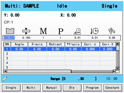
Figure 2-4 The Multi-Step page
Table 2-5lists the description of the parameter on this page. You can refer to this table when you edit the parameters on this page.
Table 2-5 The description of the parameter on Multi-Step page
| Parameter | Description |
 |
Default 1 Range 0 to 30 Unit - Description Set a desired die ID for the program. The parameters of the die can be edited on Die page. |
 |
Default 0 Range 0.000 to 99.999 Unit mm Description The thickness of the sheet. |
 |
Default 1 Range 1 to 6 Unit - Description Set a desired material ID for the program, which is used for calculating the bending depth. The parameters of the material can be edited on Material Table page. |
 |
Default 0 Range -1 to 999 999 Unit - Description The stock counter is incremented or decremented after each end of a program cycle, which depends on the settings of the parameter Count Mode. Set it to -1, indicating the stock count is disabled. Set it to other value: When the Count Mode is Cnt Down, the stock counter in production mode is decreased by 1 after each product cycle. When the counter has reached 0, the machine is stopped. When the Count Mode is Cnt Up, the stock counter in production mode is increased by 1 after each product cycle. |
| Parameter | Description |
 |
Default 0 Range 0.00 to 99.99 Unit s Description The wait time before the X-axis performs the retract. |
 |
Default 0 Range 0.00 to 99.99 Unit s Description The hold (dwell) timeof punch at the bending point. |
 |
Default 0 Range -90.00 to 90.00 Unit ° Description This parameter is valid when the bending method is angle, which indicates the correction on angle to the whole bending. For example: If the programmed value is 90, while the actual measured value is 92, then this parameter shall be set to -2. If the programmed value is 90, while the actual measured value is 88, then this parameter shall be set to 2. |
| BN | Default 1 Range 1 to 25 Unit - Description This parameter indicates the current bending step in the program. |
| Angle | Default 0 Range 0.00 to 180.00 Unit ° Description Set a desired angle value in the selected bending step. |
| X-axis | Default 0 Range 0.000 to 9 999.999 Unit mm Description The programmed value for the X-axis. |
| Retract | Default 0 Range 0.000 to 9 999.999 Unit mm Description Retract distance of the selected axis in the current bend. The "backgauge retract" is started when the beam is pinching the sheet. |
| Open | Default 0 Range 0.00 to 99.99 or 0.000 to 9 999.999 Unit s or mm Description Set the opening distance or opening time for the opening process. |
| Y-axis | Default 0 Range 0.000 to 9 999.999 Unit mm Description The programmed value for the Y-axis. |
| Parameter | Description |
| Corr.α | Default 0 Range -90.00 to 90.00 Unit ° Description This parameter is valid when the bending method is angle, which indicates the correction on angle to the current bending step. For example: If the programmed value is 90, while the actual measured value is 92, then this parameter shall be set to -2. If the programmed value is 90, while the actual measured value is 88, then this parameter shall be set to 2. |
| Corr.X | Default 0 Range -99.99 ~ 99.99 Unit mm Description When the actual axis position is not corresponding with the displayed value, it is possible to correct the position with this parameter. For example: If the programmed value is 100.00, while the actual measured value is 102.05, then this parameter shall be set to -2.05. If the programmed value is 100.00, while the actual measured value is 98.05, then this parameter shall be set to 1.95. |
| Repeat | Default 1 Range 1 to 99 Unit - Description Set the repetition times for the selected bending step. |
We take the following process as an example to describe the programming.
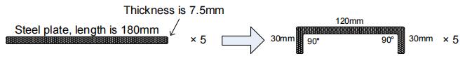
In this example, there are 2 bending steps, and we can learn a set of the basic data: material is steel; one X-axis is 30 and other is 120; bending-angle is 90; thickness is 7.5; stock is 50.
We decide to program the process by the given angle, and supposing the die ID is 1.
In addition, we can set some other necessary parameters according to our experience, such as holding time is 3, retracting delay is 2, and retract distance is 5.
Follow the below procedure to perform the program.
2. Move the cursor on (Die), and type 1.
Note: For details about the setting of the die, see the section 2.6 Die Settings.
3. Move the cursor on (Thickness), and type 7.5.
4. Move the cursor on (Material), and type 1.
5. Move the cursor on (Stock), and type 5.
6. Move the cursor on (Retr. DLY), and type 2.
7. Move the cursor on (Hold Time), and type 3.
8. Move the cursor on Angle where BN is 1, and type 90.
9. Move the cursor on X-axis where BN is 1, and type 30.
10. Move the cursor on Retract where BN is 1, and type 5.
11. Move the cursor on BN, and press ENTER key.
Then, press OK on the pop-up dialog-box to create a new bending step.
12. Then, press OK on the pop-up dialog-box to create a new bending step.
13. Move the cursor on X-axis where BN is 2, and type 120.
14. Move the cursor on Retract where BN is 2, and type 5.
15. Press START key on the operation panel.
Now, the servo-axis can start to positioning. When the machine is ready, it can be produced.
The servo axes, which are controlled by servo motor, can be moved manually with the arrow keys in
Manual page. You can perform this operation without starting the device.
Perform this operation can help you adjust or commission the machine.
To enter the Manual page, power up the device and wait for the device displays the default page, and then press F3 key, as shown in Figure 2-5.
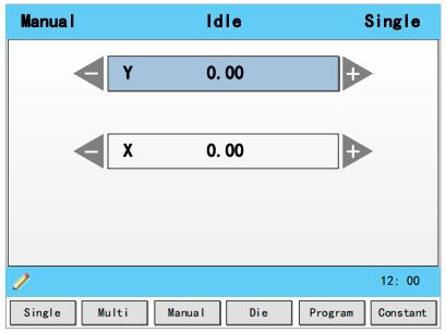
Figure 2-5 The Manual page
Press the arrow keys UP and DOWN to select the desired servo-axis.
Press the arrow keys LEFT and RIGHT to select proper movement direction.
To program the process by the given angle, it is necessary to set parameters of the die.
Press F4 key to enter the Die page, as shown in Figure 2-6.
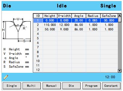
Figure 2-6 The Die page
Press arrow keys UP and DOWN to select the desired die ID.
Press arrow keys LEFTand RIGHT to select the desired parameter of the die.
Press NUMERICkeys to type the proper value.
The technical parameters diagram of the die are as shown in Figure 2-7.
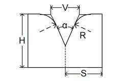
Figure 2-7 The technical parameters diagram of the die
H: The height of the die, which is used in the bend depth calculation.
V: The length of V-opening, which is the distance between the touching lines crossing.
α : The angle of the die.
R: The radius of the edges of the V-opening.
S: Safety distance, which will be used in the case an R-axis,is mounted. This to prevent finger to die collision. The indicated minimum value iscomputed automatically from the die dimensions as follows:
S = FS+V/2, in which:
FS = flat section on the back side of the V-grove
V = opening value.
It is necessary to commission the machine before your actual processing, in order to win an accurate bending result.
For performing it, you can program a bending process on Single-Step page, and operate the machine to complete one processing.
Then, measure the actual bending angle, bending depth, and the distance of the back gauge.
Check whether the bending result is corresponding with your requirement.
The range of this parameter is from -90 to 90.
When the actual axis position is not corresponding with the displayed value, it is possible to correct the position with this parameter.
For example:
When the programmed and displayed value is 90, while the actual axis positionvalue is 92, then you shall set the Corr. α to -2.
When the programmed and displayed value is 90, while the actual axis positionvalue is 88, then you shall set the Corr. α to 2.
The range of this parameter is from ﹣99.999 to 99.999.
When the actual axis position is not corresponding with the displayed value, it is possible to correct the position with this parameter.
It may be repeating to set Corr. Y. However, we can learn from experience, program the process by the given angle, and measure the depth of 1 degree as the unit length. Then, program the process by the given depth, and set Corr. Y according to the unit length. Repeat this operation, until the bending result is corresponding with your requirement.
The range of this parameter is from ﹣99.999 to 99.999.
When the actual axis position is not corresponding with the displayed value, it is possible to correct the position with this parameter.
The setting of X-axis correction is same with Angle correction. For example:
When the programmed and displayed value is 100.00, while the actual axis position value is 102.05, then you shall set the Corr. X to -2.05.
When the programmed and displayed value is 100.00, while the actual axis position value is 98.05, then you shall set the Corr. X to 1.95.
Note: The machine can stop any time in Single-Step bending, and then you can modify the programmed value of X-axis, so Corr. X is not necessary in Single-Step programming. However, there are a number of bending steps in Multi-Step programming, and Corr. X is assigned to each step.
2.8.1 Create a Program
Press F5 key to enter the Program page, as shown in Figure 2-8.
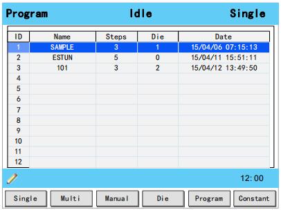
Figure 2-8 The Program page
Move the cursor on the program Name, and press NUMBERS keys to type a desired name. The typing method is 10 keys, that is, the numbers and letters on the same key can be switched by
pressing severaltimes. For example, 2, C and D are in the same key, press once, shown as 2; quickly press twice, shown as C; quickly press three times, shown as D.
Press ENTER key to confirm your typing, the software can generate the Steps, Die and Date.
2.8.2 Edit the Program
Move the cursor on the program ID you want to edit, and press ENTER key to enter the Multi-Step page. In addition, when you enter the Multi-Step page, the selected program has been loaded.
For details about the program see the section 2.4 Multi-Step.
2.8.3 Delete a Program
Move the cursor on the program ID you want to delete, and press CLEAR key. The page can display a dialog for asking whether to delete the selected item. Press OK to delete the selected program.
In order to obtain the position values of the servo axes, the user needs to perform Teaching operation before the bending process, which can indicate the current position of the servo axis.
The diagram of machine coordinate system is as shown in Figure 2-9. You can refer to this diagram to complete the teaching value of the measurement and set.
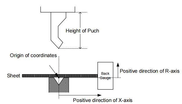
Figure 2-9 Coordinate systemof machine
Type the password 1212 in Constant page to enter TechIn Para page, as shown in Figure 2-10.
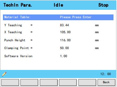
Figure 2-10 TechIn Para page
Press the arrow keys UP and DOWN to select a parameter, and type the desired value for them.
The purpose of teaching Y-axis is obtaining the comparativeposition value of clamping point. When you teach Y-axis, it is necessary to estimate the position value of the Y-axis in advance. For example, if the position of the Y-axis is estimated to be 50mm, and the procedureis as follows:
Step 2 Select the parameter Y Teaching in TechIn Para page, and set it to 50.
Step 3 Return to the Single-Step page, and set the parameter Angle to 180, and the other parameters can be set arbitrarily.
In general, when the machine is in clamping, the punch just against the top of the sheet, so the bending Angle is set to 180, in order to ensure that the sheet was clamped.
Step 4 Run the device, and record the Y-axis position displayed on the device when the process is in Dwell.
Step 5 Enter the TechIn Parapage again, and fill the recorded value in the parameter Clamping Point.
Note: The relationbetween Y Teaching and Clamping Point is comparative. If the position of Y-axis has been changed, you must perform the above procedure for obtaining the value of Clamping
Point again.
----End
To teach the X-axis, you can measure the actual position of the X-axis, that is to say, measure the linear distance between the V-opening center of the die and back gauge.
Although there are many methods for teaching X-axis, their purpose is to ensure the processing accuracy. It is recommended that the user can run the machine once after roughly measuring the
distance, that is, program a simple Single-Step program. For example, the measurement of the X-axis distance of 100mm, and the procedureis as follows:
Step 6 Select the parameter X Teaching in TechIn Parapage, and set it to 100.
Step 7 Return to the Single-Step page, and set the parameter X-axis to 100, and the other parameters can be set arbitrarily. Here we need not to consider the error from the machine itself.
Step 8 Run the machine. When the bending step has been completed, measure and record the worked sheet.
Step 9 Enter the TechIn Para page again, and fill the recorded value in the parameter X Teaching.
Note: It is necessary to perform the above procedures for several times for ensuring the accuracy of the working.
----End
To teach the R-axis, you can measure and record the actual position of the R-axis directly, that is, measure the vertical distance between the top of the die and the back gauge. Then, enter the TechIn Para page again, and fill the recorded value in the parameter R Teaching.
Press START key to startup the machine when you complete the program on Single-Step page or Multi-Step page, the servo-axis can start to positioning. When the machine is ready, it can be
produced.
However, it is unavailable to press START key on other pages.
When the device is running, its indicator lamp can be lighting. In addition, you can see the status on the top of page is RUN.
There are 3 cases for stopping the device.
Stop by a fault: If any fault occurred during the operation, the machine can stop automatically. Normally Stop: it also includes the following case:
Manual stop: press STOP key, the running machine can stop.
Count is finished: for the Count Mode is Cnt Down, when the Stock is 0, the running machine can stop automatically.
Emergency Stop: press down EMERGENCY STOP button, the power supply of the system can be cut off.
When the device is stopped, its indicator lamp can be lighting. In addition, you can see the status on the top of page is Idle or Alarm.
As shown in Figure 3-1, which indicates a fault had occurred during the operation. It is necessary to solveit for recovering the running machine.
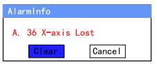
Figure 3-1 An alarm information occurred
Follow the section Appendix D Alarm List, solving the fault according to the fault message, and then move the cursor on Clear, and press ENTER key, so that the system can try to reset.
However, the fault message may display again if the fault hasn’t been solved properly.
Move the cursor on Cancel and press ENTER key, the AlarmInfo dialog-box can be hiddentemporarily. To display it again, press CLEAR key when the page is on SingleStep or Multi-Step.
You can view the ports allocation, valve status and fault list on Status Monitor page.
Press and hold STARTkey for 3 seconds when the machine is running.
Press and hold STOP key for 3 seconds when the machine is not running.
When you enter Status Monitor page, you can view the Valve Status tab, as shown in Figure 3-2

Figure 3-2 Valve status monitored
On Valve Status tab, you can view the output status of valves. Blue background ![]() indicates the port is turned ON while Blank indicates the port is turned OFF.
indicates the port is turned ON while Blank indicates the port is turned OFF.
You can view the current valve status on Curr.row, and the other rows shows the allocation in corresponding process.
For example, you have allocated the process Press as YV1 and YV3, when the machine is in Press process, the Curr.Row displays ![]() on YV1 and YV3.
on YV1 and YV3.
Press arrow key RIGHT on the Valve Status tab, you can view the IO Status table, as shown in Figure 3-3.
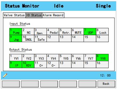
Figure 3-3 IO status monitored
Green background ![]() indicates the port is turned ON, while Blank indicates the port is turned OFF.
indicates the port is turned ON, while Blank indicates the port is turned OFF.
Press arrow key RIGHT on the IO Status tab, you can view the Alarm Record table, as shown in Figure 3-4.

Figure 3-4 Alarm history page
ID: numbering for the alarm list, descending sort by Alarm Date, i.e. ID 1 is the latestfault message.
Alarm Num: to show the code of the fault. For detail about solving the faults, see the section.Appendix D Alarm List.
Alarm Reason: to show summary recordof the fault.
Alarm Date: to show when this fault occurred.
The commonly used parameters are displayed on Constant page, as shown inFigure 3-5.
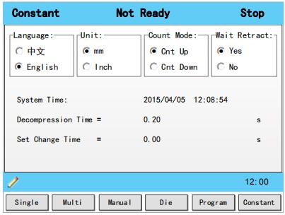
Figure 3-5 The Constant page
Table 3-1 list these parameters and their description.
Table 3-1 The description of the parameters onConstant page
| Parameter | Description |
| Language | Select a desired language for the pages. |
| Unit | Select a desired length scale for the dimensions. E300 can convert the current dimensions automatically when you change this parameter. |
| Count Mode | Select a desired stock count mode. To select Cnt Up, the stock counter in production mode is increased by 1 after each product cycle. To select Cnt Down, the stock counter in production mode is decreased by 1 after each product cycle. When the counter has reached 0, the control is stopped. Down counting can be useful if a pre-planned quota must be produced. Up counting could be used to give a report on production progress. |
| Wait Retract | In the case of a retract, let the Y-axis wait until the retract is finished. To select Yes, when the Y-axis reaches the clamping point, the Y-axis is stopped and the retract is started. When the retract is completed, the Y-axis moves on. To select No, the retract is started when the Y-axis passes the clamping point, the Y-axis does not stop. |
| System Time | Set to a proper time for the system. The format is yyyy/MM/ddHH:mm:ss. For example, 2015/11/23 14:51:00. |
| Decompression Time | Set the durationfor the decompression process. This parameter affects the time for tuning ON the valve of Decmp. |
| Set Change Time | Set a waiting time for entering next step when the previous step is completed. |
| Intermediate R | Temporary position for the R-axis, to avoid collision as a result of movement of the X-axis. The value 0 disables this functionality. When programmed not equal to zero thisposition will be active when the X-axis has to move inside the safety zone of the die. The sequence will be as follows: a. The R-axis is moved to the intermediate position; b. then the X-axis is moved to its intended position; c. finally the R-axis is moved to its intended position. 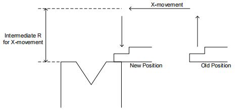 |
| Glossary | Description |
| Axis | A reference direction, which can make the parts of the machine do the linear motion or rotation motion. |
| Machine Coordinate System | Cartesian coordinate system based on machine zero, which is fixed on the machine. |
| Computerized Numerical Control, CNC |
Fulfill the numerical control the processing functions by the computer. |
| Reference Position | A fixed point along the axis, which can be referenced to the origin of the machine. |
| Hardware Limit | A limit position, which is mounted in the machine, can limit the movement of the parts. |
| Software Limit | A limit range, which is programmed in the device, can limit the movement of the parts. |
| Mute | A position where the process switches from Fast-Closing to Pressing. |
| DA (Digital to Analog) | To convert the Digital signal into the Analog signal. In general, decode the digital signal and convert into a corresponding level, which can form a step shape signal, and then perform a low-pass filtering. |
| AD (Analog to Digital) | To convert the Analog signal into the Digital signal. The analog signal is subjected to a line filter, and then samples the hold circuit to be a step shapesignal, and then the step shape signal is converted into a binary code by the encoder, that is, the desired digital signal. |
| UpperDead Point, UDP | The critical position for the movement of the beam, where the beam cannot continue to move upwards. |
| Punch | Also known as male mold, which is a die part forming the shape of the end face. |
| Die | Also known as female mold, which is a die part forming the shape of the outer. |
| Lower Dead Point, LDP | The critical position for the movement of the beam, where the beam cannot continue to move downwards.The theoretical position is at the lowest point of the V-Opening. |
| Fast Closing | One process of the bending step, which can make the beam moves to Mute fast. |
| Pressing | One process of the bending step, which can make the beam moves from Mute to bending point. |
| Dwell | In order to ensure the formation of the workpiece, it is necessary to keep the pressure for a period of time when the punch has been reached the bending point, against the tensile strength of the material. |
The double asterisk (**) at the front of the parameter indicates this parameter is displayed when you have updated the function.
| Language | Default 中文 Range 中文; English Unit - Description Select a desired language for the pages. |
| Unit | Default mm Range mm; Inch Unit - Description Select a desired length scale for the dimensions. E300 can convert the current dimensions automatically when you change this parameter. |
| Count Mode | Default Cnt up Range Cnt up; Cnt Down Unit - Description Select a desired stock count mode. To select Cnt Up, the stock counter in production mode is increased by 1 after each product cycle. To select Cnt Down, the stock counter in production mode is decreased by 1 after each product cycle. When the counter has reached 0, the control is stopped. Down counting can be useful if a pre-planned quota must be produced. Up counting could be used to give a report on production progress |
| Wait Retract | Default Yes Range Yes; No Unit - Description In the case of a retract, let the Y-axis wait until the retract is finished. To select Yes, when the Y-axis reaches the clamping point, the Y-axis is stopped and the retract is started. When the retract is completed, the Y-axis moves on. To select No, the retract is started when the Y-axis passes the clamping point, the Y-axis does not stop. |
| System Time | Default - Range - Unit - Description Set to a proper time for the system. The format is yyyy/MM/ddHH:mm:ss. For example, 2015/11/23 14:51:00. |
| Decompression Time | Default 0.20 Range 0.00 to 99.99 Unit s Description Set the durationfor the decompression process. This parameter affects the time for tuning ON the valve of Decmp. |
| Set Change Time | Default 0 Range 0.00 to 9.99 Unit s Description Set a waiting time for entering next step when the previous step is completed. |
| ** Intermediate R |
Default 5 Range 0.00 to 99.99 Unit mm Description Temporary position for the R-axis, to avoid collision as a result of movement of the X-axis. The value 0 disables this functionality. When programmed not equal to zero thisposition will be active when the X-axis has to move inside the safety zone of the die. The sequence will be as follows: a. The R-axis is moved to the intermediate position; b. then the X-axis is moved to its intended position; c. finally the R-axis is moved to its intended position. 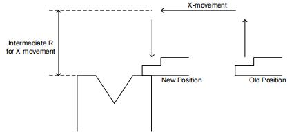 |
| ID | Default - Range 1 to 6 Unit - Description The number of the material, which shall be set on the programming page. |
| MatName | Default - Range Steel; Aluminum; Zn; Stainless Steel; Material5; Material6. Unit - Description The name of the material, which is unable to set. |
| TStrength | Default - Range 0 to 9999999 Unit N/mm2 Description The tensile strength of the selected material. |
| EModulus | Default - Range 0 to 9999999 Unit N/mm2 Description The elastic modulus of the selected material. |
| Y Teaching | Default 0 Range 0.000 to 9999.999 Unit mm Description Set a taught position for Y-axis. See the section 2.9 Teaching to perform the teaching operation. |
| X Teaching | Default 0 Range 0.000 to 9999.999 Unit mm Description Set a taught position for X-axis. See the section 2.9 Teachingto perform the teaching operation. |
| ** R Teaching |
Default 0 Range 0.000 to 9999.999 Unit mm Description Set a taught position for R-axis. See the section 2.9 Teachingto perform the teaching operation. |
| Punch Height | Default 0 Range 0.000 to 9999.999 Unit mm Description Set this value according to the technical parameters of the punch. |
| Clamping Point | Default 0 Range 0.000 to 9999.999 Unit mm Description Set a taught position for the clamping point. See the section2.9 Teaching to perform the teaching operation. |
| Software Version | Default - Range - Unit - Description Display the current version of the software. |
| Name | Default - Range The maximum length is 12 characters, which may contain letters and numbers as available on the keyboard. Unit - Description A unique name to identify a product program. |
|
Die
|
Default 1 Range 0 to 30 Unit - Description Set a desired die ID for the program. The parameters of the die can be edited on Die page. |
|
Material
|
Default 1 Range 1 to 6 Unit - Description Set a desired material ID for the program, which is used for calculating the bending depth. The parameters of the material can be edited on Material Table page. |
| Thickness |
Default 0 Range 0.000 to 99.999 Unit mm Description The thickness of the sheet. |
|
Hold Time
|
Default 0 Range 0.00 to 99.99 Unit s Description The hold (dwell) timeof punch at the bending point. |
|
Retr.DLY
|
Default 0 Range 0.00 to 99.99 Unit s Description The wait time before the X-axis performs the retract. |
|
Stock
|
Default 0 Range -1 to 999 999 Unit - Description The stock counter is incremented or decremented after each end of a program cycle, which depends on the settings of the parameter Count Mode. Set it to -1, indicating the stock count is disabled. Set it to other value: When the Count Mode is Cnt Down, the stock counter in production mode is decreased by 1 after each product cycle. When the counter has reached 0, the machine is stopped. When the Count Mode is Cnt Up, the stock counter in production mode is increased by 1 after each product cycle. |
|
Default 0 Range -90.00 to 90.00 Unit ° Description This parameter is valid when the bending method is angle, which indicates the correction on angle to the whole bending. For example: If the programmed value is 90, while the actual measured value is 92, then this parameter shall be set to -2. If the programmed value is 90, while the actual measured value is 88, then this parameter shall be set to 2. |
| Steps | Default 1 Range 1 to 25 Unit - Description This parameter displays how many steps in the selected program. |
| BN | Default 1 Range 1 to 25 Unit - Description This parameter indicates the current bending step in the program. |
| X-axis | Default 0 Range 0.000 to 9 999.999 Unit mm Description The programmed value for the X-axis |
| Y-axis | Default 0 Range 0.000 to 9 999.999 Unit mm Description The programmed value for the Y-axis. |
| ** R-axis |
Default 0 Range 0.000 to 9 999.999 Unit mm Description The programmed value for the R-axis. |
| ** C-axis |
Default 0 Range 0.000 to 9 999.999 Unit mm Description The programmed value for the C-axis. |
| Retract | Default 0 Range 0.000 to 9 999.999 Unit mm Description Retract distance of the selected axis in the current bend. The "backgauge retract" is started when the beam is pinching the sheet. |
| Corr.α | Default 0 Range -90.00 to 90.00 Unit ° Description This parameter is valid when the bending method is angle, which indicates the correction on angle to the current bending step . For example: If the programmed value is 90, while the actual measured value is 92, then this parameter shall be set to -2. If the programmed value is 90, while the actual measured value is 88, then this parameter shall be set to 2. |
| Corr.Y | Default 0 Range -99.99 to 99.99 Unit mm Description Correction on the Y-axis position, in case absolute programming is used or bottoming is selected for a bend. |
| Angle | Default 0 Range 0.00 to 180.00 Unit ° Description Set a desired angle value in the selected bending step. |
| Repeat | Default 1 Range 1 to 99 Unit - Description Set the repetition times for the selected bending step. |
| Open | Default 0 Range 0.00 to 99.99 or 0.000 to 9 999.999 Unit s or mm Description Set the opening distance or opening time for the opening process. |
| Height | Default 0 Range 0.000 to 999.999 Unit mm Description The length from the top to the bottom of the die. |
| V-width | Default 0 Range 0.000 to 999.999 Unit mm Description The length from the top to the bottom of the die. |
| Angle | Default 88 Range 0.00 to 180.00 Unit ° Description The angle of the V-opening. |
| Radius | Default 1 Range 0.000 to 999.999 Unit mm Description The radius of the V-opening edges. |
| SafeZone | Default 10 Range 0.000 to 999.999 Unit mm Description To prevent back gauge to die collision, the movement of the R-axis shall be kept in this value add half of V-width. |
As shownFigure C-1andFigure C-2, you can view two timing charts, which are taken one ordinary bending step as the examples for representing the working status of each component.
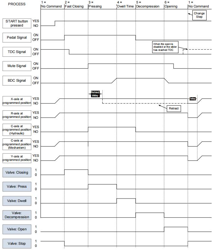
Figure C-1 Timing Chart A

Figure C-2 Timing Chart B
Note:
In the case of retracting, let the Y-axis wait until the retract is finished, you shall set the parameter Wait Retract to Yes.
When the beam has reached the TDC in opening, the TDC signal can be turned ON and the beam stops the moving.
If you have set the parameter Retract in your programming, the X-axis can start retracting when the Retr.DLY time has been finished. Then, the X-axis will not reposition until the next step is started.
The opening time is started when the Mute Signal is turned from ON to OFF.
--- End
![]()
Masters in industrial manufacturing with 25 years of experience and 10+ awards!