Krrass customer support team is here to answer your questions. Ask us anything!
Hi, how can I help?
Warning!
When using the machine tool, basic safety precautions should always be followed to reduce the risk of fire, electric shock and personal injury.
Read all instructions before attempting to operate this machine and keep these instructions.
Don’t remove this sign and operation manual!
Catalog
We suggest all users and operators to read this operation manual carefully before using this machine.
This manual is designed for specialized and qualified personnel. It comes completes with diagrams and all the documentation necessary to lift, move and place the machine and instructions for the safe use and maintenance of this machine. All information contain in here are accurate at the time of print. However, our company reserves the rights to modify and improve specifications without prior notice.
This machine should be properly installed as instructed; regular inspection and faithful maintenance service should be carried out so that good performance can be maintained.
Any incorrect and irresponsible usages may cause irreparable damage to the machine and nullify the safety protection for the operator.
We do not assume any responsibility for improper services or modifications or connections made by unauthorized personnel.
We suggest that all user to read and understand this manual before using this machine.
3.1 Packing / Shipment of machine
All machines leaving the factory are packed with squaring arm and foot panel tied to the hand guard. A bag of working hand tools and operation manual is lock inside the electrical panel.
All exposed surfaces on machine are coated with rust guard, easily removable by kerosene or solvent.
3.2 Lifting the machine
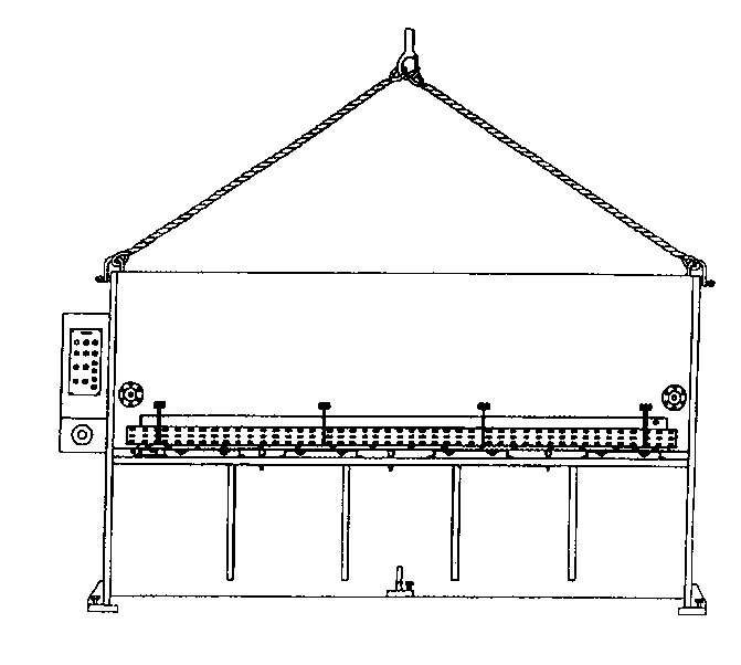
Use only approved and safe wire rope to lift this machine from two lifting point which is located at both side frame of the machine.
3.3 Foundation
All our shears are designed to be free standard. However, a good quality reinforced concrete floor with a minimum thickness of 150mm should be used.
3.4 Installation
This machine must be properly leveled to give a good cut. Leveling is done by putting a good leveling gauge at the plate hold down area. Always pre-prepare five pieces of base plate (dimension 150 x 150 x 9mm, minimum) below machine footing to prevent leveling screw from digging into the concrete floor.
On completion of leveling, a cement grout mixture must be packed under and around the feet to maintain correct leveled position.
3.5 Electrical Installation
Be sure that the local power supply is suitable for this machine before any electrical power up. Connect power cable to the bottom left of electrical panel to R.S.T.E. terminal.
Some machine may require N (Neutral) wire.
| 5.1 | Start button | : | To start the main motor running and Control circuit. | ||
| 5.2 | Stop button | : | To stop the main motor running and Control circuit. | ||
| 5.3 | Auto/Man mode selector switch | : | Select the working mode | ||
| In Auto mode | -Rake angle adjustment function able | ||||
| -Motorized back gauge function able | |||||
| -Can command cut by foot pedal only. | |||||
| In Man mode | -Rake angle adjustment not- Function able. | ||||
| -Motorized back gauge not-function able. | |||||
| -Command up and down of top blade carrier by push button ‘’ or ‘¯’. | |||||
| 5.4 | Foot pedal | : | Push to command cutting blade down and release to have top blade carrier rise in AUTO mode. | ||
| 5.5 | Illumination Light | : | Working light to shine at cutting blade area, operating at single phase power supply at 220V, 50Hz.. | ||
Remove the squaring arm and foot pedal from hand guard area. Set up the squaring arm on left hand side (Close to electrical panel) by bolting down to the machine table and two side holes.
7.1 Blade Clearance Table
| Quick blade Clearance setting | For material thickness | Blade clearance | ||
| Top position | 1 to 2 mm | ( 1/24’’ to 1/12’’ ) | 0.05mm | (0.002”) |
| 2nd position | 3 to 4.5 mm | ( 1/8” to 3/16’’ ) | 0.3 mm | (0.012”) |
| Lowest position | 5 to 6.5mm | (5/24” to 13/48’’ ) | 0.6 mm | (0.023”) |
7.2 Check for Maximum Clearance
7.3 Check for Minimum Clearance
Switch selector switch to ‘MAN’ mode.
Be sure that quick blade clearance levers are set at 2nd position (3mm).
Push ‘¯’ button until top blade carrier goes to the lowest position.
Bring quick blade clearance levers to the top position (1mm).
Push ‘’ button until interception point at end of cut.
Make measurement with feeler gauge, it should be 0.05mm (0.002”).
Push ‘’ button until the interception point at start of cut, take measurement, it should read 0.05mm (0.002”).
7.4 Attention
Only experienced and skilled personnel should be allowed to perform blade clearance checking. Recommended having two persons work together. The back gauge should be set to the rear (maximum out).
Greatest care must be exercised when setting / check the blade clearance, otherwise may cause excessive blade damage or injuries to personnel.
8.1 Lubrication and Hydraulic Oil
This machine uses hydraulic oil grade 68, refill or replace only with same grade of oil as follow:
FIAT-HTF 68, ENERGOL HLP 68, ESSO NUTO H68, MOBIL-DTE OIL 26, SHELL-TELLUS S68, TOTAL-AZOLLA 68
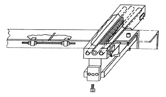
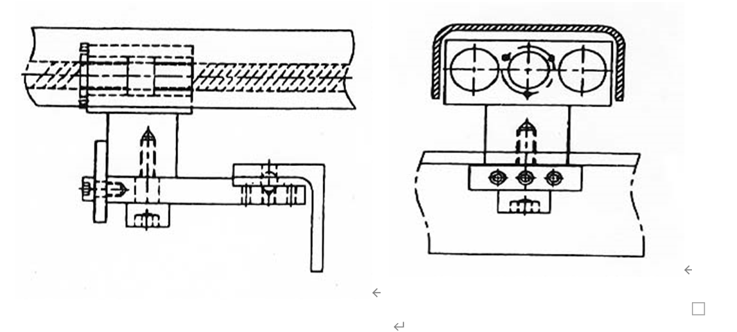
The back gauge is calibrated correctly in our factory. But it can calibrate when necessary. Following describe the method to adjust parallelism of back gauge.
-Always loosen M14 screw before any adjustment
-To reduce back gauge dimension screw in M8 screw, then tighten two M6 screws.
-To increase back gauge dimension screw out two M6 screws then tighten M8 screw.
-Tighten M14 screws after calibration is done.
8.4 Changing of Shear Blade
Both top and bottom shear blades are identical and inter changeable.
Always put blade clearance to the largest (lowest position).
Put machine in ‘AUTO’ mode and remove wires ‘F’ and ‘S’ from terminal block. This is to prevent any unwanted down command of cutting action while working on it.
OFF the machine. Remove bottom blade first then the top blade.
Release all small set screw on top blade carrier.
Clean blades and blade housing / sitting.
Fix back top blade first then bottom blade.
Tighten the small sets screw on top blade carrier if necessary to close in blade clearance.
Remember to check for minimum clearance, adjust small set screw to close up blades when require.
Remember to put back wires ‘F’ and ‘S’ to their original position before putting machine back to working condition.
CAUTION: Always engages a qualified and experiences personnel to do
this job, otherwise damage to shear blades/machine or personnel injuries may result.
8.5 Grinding of Shear Blade
The Shear blade is rectangular in shape and has four cutting edges.
Only after all four edges are used up then you require regrinding of blade.
REMEMBER: Grind only the thickness and not the height of blade.
May require to close in top blade carrier by screw in tensioning bolt as a result of the loss of Grind-off thickness of the shear blades. (next to quick blade clearance lever).
9.2 Electrical System
9.3 Motorized back gauge
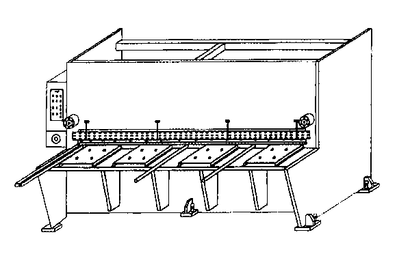
11.1 Hydraulic Shearing Machine
11.2 (A) FRONT VIEW

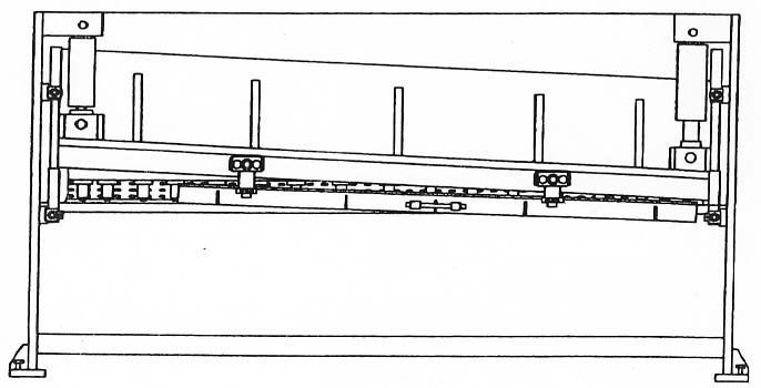
11.2 (B) REAR VIEW
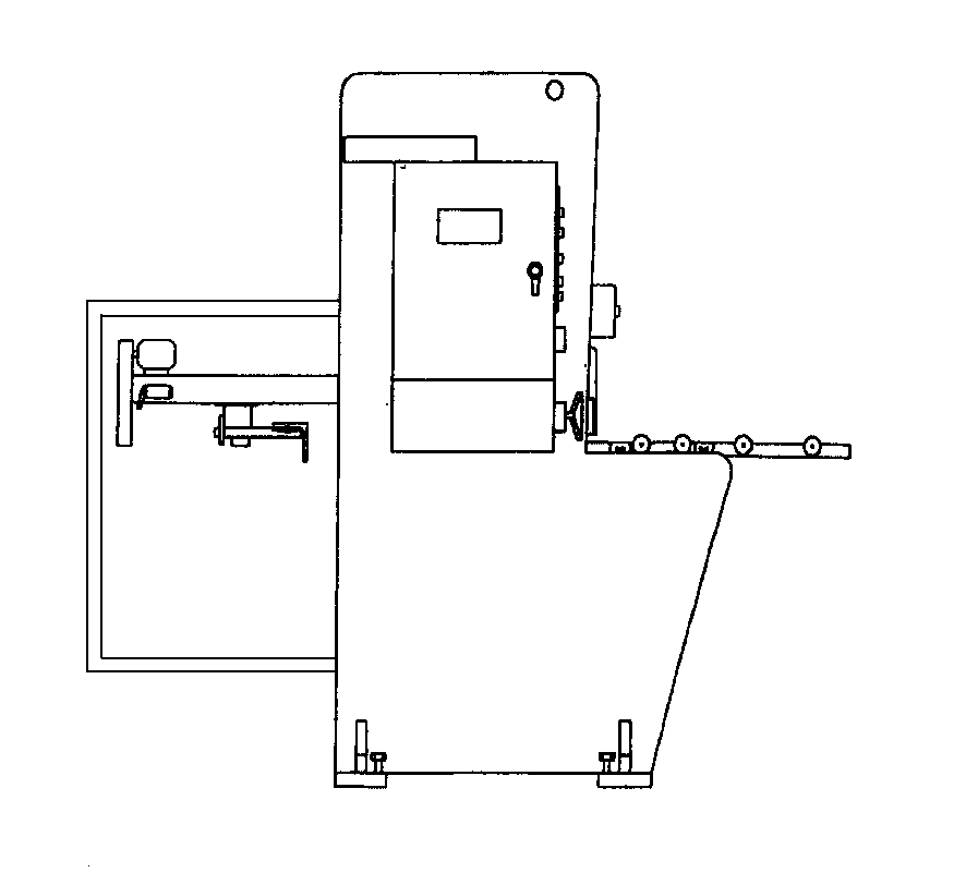
11.3 SIDE VIEW
11.4 LIFTING OF MACHINE
11.5 PLACING OF LEVELING GAUGE
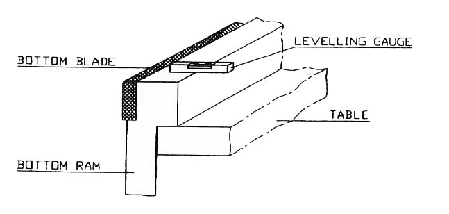
NOTE: MAKE SURE THE LEVELING GAUGE, NOT TOUCHING THE BLADE AND PLACE IT AS SHOWN ABOVE
11.6 (A) BACK-GAUGE ASSEMBLY
11.6 (B) SIDE VIEW 11.6 (C) REAR VIEW
Pre-adjust inspection
| No. | graph | Inspection program | Permission error | Inspection tools | Real value | Inspection ways |
| G1 |  | Coincidence gap between blade and sharp | 0.06 I class 0.10/1000 II class 0.02/1000 III class 0.50/1000 | Clearance gauge | Inspection clerk | When blade board move between up and down blade coincidence, if two gap of two section is equal, from 50mm, measure the gap & per 150mm. The error is max gap value minus min gap value. |
| G2 | 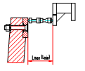 | Parallelism Between low-blade and back gauge | I class 0.10/1000 II class 0.02/1000 III class 0.50/1000 | Clearance gauge inside diameter micrometer | Inspection clerk | Adjust the mouth of front feed clamp to max or min, measure the distance between back gauge and low-blade, at least 3 spot per one meter, error value is max reading per one meter. |
| No. | graph | Inspection program | Permission error | Inspection tools | Real value | Inspection ways |
| P1 | 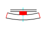 | linearity | 0.25/1000 | Level ruler level table clearance gauge | Inspection clerk | Put test pieces on level table, 1000mm length level ruler depend on cutting surface of test pieces, measure the gap by clearance gauge. Error is max reading value. |
| P2 |  | Parrel | 0.15/1000 | Vernier slide calliper | Inspection clerk | Measure the width of test pieces by vernier slide calliper(at least 3spot per one meter), error is max reading value on any 1000mm. |
Note: 1.the accuracy test duty according to this rule is not real test duty. For fix and dismantle inspection tools conveniently, can be according to any duty.
Demand of test pieces to work accuracy
iii) At 10 times as thickness from section, need not test.
![]()
Masters in industrial manufacturing with 25 years of experience and 10+ awards!