Krrass customer support team is here to answer your questions. Ask us anything!
Hi, how can I help?
Warning!
When using the machine, basic safety precautions should always be followed to reduce the risk of fire, electric shock and personal injury.
Read all instructions before attempting to operate this machine and keep these instructions.
Safety notes!
Error operation may cause die or serious injure.
Fault operation may cause mid-grade harm, flesh wound or damage.
There are emergency stop buttons on the handle control station. When there happens error operation or other accidents, push the emergency stop button, the machine will power off.
Catalogue
2.1 Lifting
2.2 Transport
2.3 Installation
4.1 Clean the hydraulic Oil
4.2 Choose the hydraulic oil
4.3 Fill the oil
6.1 Turn the machine on
6.2 Turn the machine off
6.3 Upper and lower tool setting
6.4 Mechanical depths stop setting
6.5 Pressure setting
6.6 Parallelism control and setting
7.1 Machine can not start
7.2 Ram could not be lower
7.3 Bending angle not even on entire bend length
8.1 Hydraulic oil
8.2 Oil Filter
8.3 Lubrication
8.4 Electrical terminal
8.5 Mechanical parts
9.1 Light Beam/Laser Beam
9.2 Safety grid
9.3 Emergency stop
9.4 Hydraulic system
9.5 Troubleshoot
Please be note:
We reserves the right to change the content of this manual without notice, every effort has been made to ensure that this manual is correct in every detail.
Introduction!
We suggest all users and operators to read this operation manual carefully before using this machine.
This manual is designed for specialized and qualified personnel. It comes completes with diagrams and all the documentation necessary to lift, move and place the machine and instructions for the safe use and maintenance of this machine. All information contain in here are accurate at the time of print. However, our company reserves the rights to modify and improve specifications without prior notice.
This machine should be properly installed as instructed; regular inspection and faithful maintenance service should be carried out so that good performance can be maintained.
Any incorrect and irresponsible usages may cause irreparable damage to the machine and nullify the safety protection for the operator.
We do not assume any responsibility for improper services or modifications or connections made by unauthorized personnel.
1.1 This machine is high-efficiency and high-precision in bending metal sheet. The opening size of V-gutter on lower dies is usually eight times larger than the sheet thickness, it should be regulated for sheets in different thickness. Using different kinds of upper and lower dies can bend many kinds of work pieces (See Fig.1).
1.2 The machine is structured in steel plate fabrication with sufficient strength and rigidity. The hydraulic drive prevents the machine from serious overload operation accidents caused by the change of sheet thickness or bad choice of lower die cavity. Additionally, this machine is also featured by the steadiness of work, convenience of operation, and reliable safety. The connecting section to the upper die is provided with compensation device, which compensates the deflection of worktable and slider in bending and guarantees the high work precision. Meanwhile, the mechanic block is equipped in the oil cylinder to ensure the fixing accuracy when the slider travels to the bottom dead point and so as to assure the consistency of bending angle in bulking production.
1.3 It is equipped with hydraulic electric control, freely adjustable slider travels and inch operating criterion convenient for module trial and adjustment.
1.4 This machine is advanced in technology and reliable in performance, and among the ideal shaping apparatuses. It is widely used in plane, automobile, shipbuilding, and machine with high production efficiency.
1.5 Operation condition:
Temperature: 5~38℃(Working temperature)
Environment moisture: Relative moisture 20~80%RH。
Keep far away from powerful vibration and electromagnetic interference.
No pernicious and corrosiveness gas, and no dust.
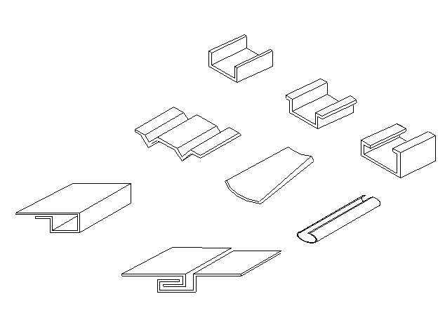
Fig.1
2.1 Lifting
It must be ensured that when lifting the press-brake for transportation and/or positioning it must be done with crane having sufficient lifting capacity so that there will be no risk of the press-brake falling.
When lifting use two slings of steel rope and shackles using the appropriate holes available at the top of the machine. The steel rope must be of an adequate size to lift the weight of the press-brake. It must also be of an adequate length, given that its weight carrying capacity diminishes when the angle between the ropes widens. (See Fig. 2)
2.2 Transport
When transporting the press-brake, keep in mind that the weight of the machine is concentrated mainly to the front. Ensure that the top ram of the press-brake is all the way down for manoeuvres or transportation.
When the press-brake is to be load onto the truck , the rear side of the machine is position as far as possible to the side of the vehicle.
The press-brake is to be anchored to the truck using steel rope
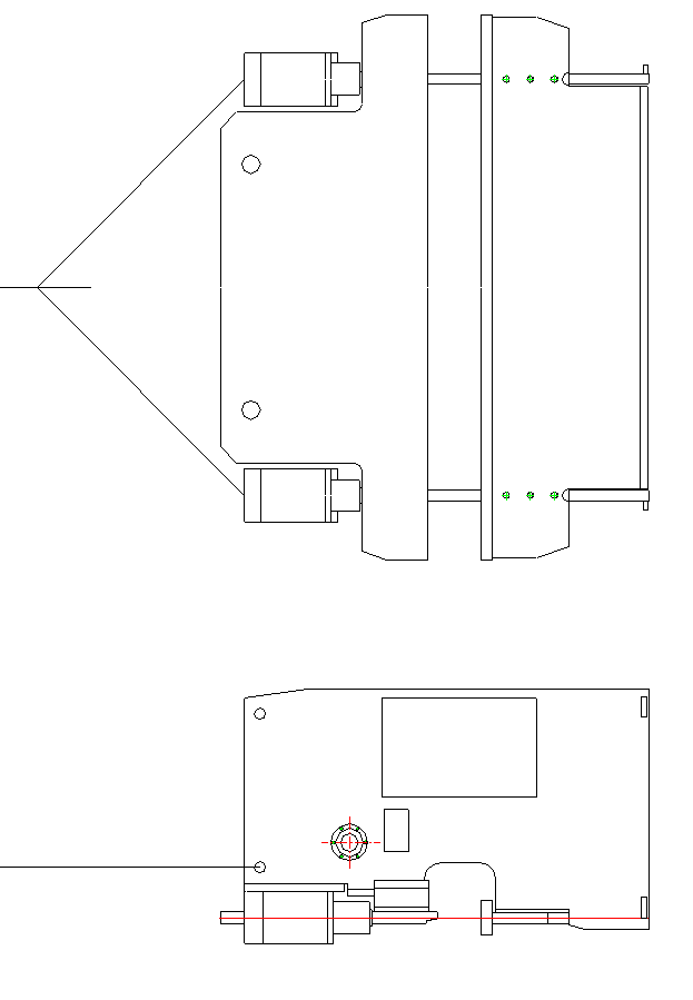
Fig. 2
2.3 Installation
2.3.1 The foundation
To ensure that the machine works correctly and is not disturbed by vibrations check that the pavement is firm and steady. Prepare a concrete foundation, which must be adapted to the conditions of the ground, if necessary. And detail drawing of foundation as attachment.
Ensure that there must be adequate space surrounding the machine once position. This is necessary to cater for maintenance work and special jobs. Furthermore, an adequate space on either the left or right side of the press-brake equals to the length of the machine to cater for tool changing operation.
All exposed surfaces on machine are coated with rust guard, easily removable by kerosene or solvent.
2.3.2 Leveling
For the press-brake to function correctly, it is necessary that the machine be leveled correctly.
Eventual adjustments are done by regulating the leveling bolts in the feet of the press brake
3.1 The following steps are to be cared for by the owner and must be carried out by specialized personnel.
Note: To guarantee the safety, machines with CE certificat without continuity mode.
4.1 Clean the hydraulic Oil
The hydraulic system has high requirement for the cleanliness of hydraulic oil. The clean of oil tank is very important.
When replace the hydraulic oil, you must discharge the cover of oil tank. Use the towel to clean the bottom of tank (do not use cotton yarn), then wash with cleaning coal oil gasoline. For limitation of tank cover, the arm cannot reach the end of tank; you can wrap the towel on the bamboo or stick to wipe each corner. Loosen the leaking plug or brake valve to leak out the dirt oil.
Use the cleaning towel to dry the sides and bottom of tank until it’s clean. If necessary, roll the dough at the welding seam or difficult cleaning places to cling the dirt, and then put on the cover.
4.2 Choose the hydraulic oil
The mark value of hydraulic oil is equal to the average value of viscosity, when the temperature is 40℃.
If the working pressure and temperature of hydraulic system is higher, and the working speed is slower, the chose hydraulic oil mark is higher.
It is recommended to use antiwar hydraulic oil ISO VG46# (the average value of viscosity is 46mm2/s, when the temperature is 40℃.). If the machine operates under 5℃ for a long period, you can choose hydraulic oil ISO VG32#.
It is also recommended not to use the machine at very low temperatures (below -5°). However, should this occur, and then let the machine run idle for a while. An oil heater can be fitted in circuit if required.
Under the normal working conditions the oil temperature must not exceed 70C. Under special conditions, oil cooler can be fitted necessary.
4.3 Fill the oil
The using oil must clean. Screw the nut of air filter, filling through air filter. If using the filling equipment with filter, you can open the cover of oil tank and fill directly. Observe oil gauge, when ram stops at Top Dead Spot, the hydraulic oil fills at 80~90% of interspaces.
Make the machine work, first idling then at maximum stroke to expel any air bubbles in the hydraulic circuit.
| 5.1 | Start button | : | To start the main motor running and Control circuit. |
| 5.2 | Stop button | : | To stop the main motor running and Control circuit. |
| 5.3 | Auto/Manual Mode Selector Switch | : | Select the working mode |
| In Auto mode | -The ram will rise automatically when Preset pressure is reach and the dwell time is up. | ||
| In Manual mode | -Lowering and raising of the ram is by pressing the foot pedal. | ||
| 5.4 | Foot pedal | : | Push and hold to command lowering the ram to reach bending point, release when the ram is moving up in AUTO mode. |
| : | Press to command lowering the ram and press to command raising the ram in Manual mode. | ||
Prior to the start-up of the machine, please check the following
6.1 Turn the machine on
6.2 Turn the machine off
The press-brake must always be turned off when left unused for a few hours. When turning off, do the following:
6.3 Upper and lower tool setting (Tooling drawings See the attachments)
The upper tool and the selected V – opening must be aligned before any bending commence to ensure good bending result. Ensure that the V-die base and table surfaces are clean before the following
Steps is carry out.
We advice the following:
Tools Change Procedure
÷TOP TOOL
When the top tool need to be change, do the following:
÷LOWER TOOL
When need to change a different vee on your multi-vee die, do the following:
÷FRONT SUPPORT ARM
The press brake is supplied with two front support arms as standard equipment. These are used for placing the plate on during the various bending phases. They can be adjusted vertically and along the length of the press brake. Support arms generally need to be adjusted when a different size bottom tool is used or a larger or smaller size plate is being bent.
DANGEROUS!
IF THE PUNCH AND DIE ARE NOT PLACED CORRECTLY, YOU MUST NOT START THE MACHINE, ANY TIME, DON’T PULL YOUR HANDS OR ANY PARTS OF BODY INTO THE SPACE BETWEEN PUNCH AND DIE, IT IS VERY DANGEROUS!
6.4 Mechanical depths stop setting
DO NOT ATTEMPT TO ADJUST THE MECHANICAL DEPTH STOP SETTING WHEN THE RAM IS AT THE DOWN POSITION AS THIS MAY CAUSE UNNECESSARY DAMAGE TO THE MACHINE.
6.5 Pressure Setting
Normally the bending chart is fixed on the side of the machine, a copy is enclosed. The bending force is function of :
-The plate thickness
-The width of the die opening. ( 8 x plate thickness )
The required bending force can be computed from the Table 1 formulate.
Table 1 Bending Pressure

Note: This formula and the values in table are all based on carbon-steel plates with tensile strength Qb=450KN.
Stainless steel plate: the P value from table multiply by 2
Aluminum plate: the P value from table multiply by 0.7
6.6 Parallelism control and setting
The parallelism of the ram is control by a solid anti-torsion bar, which is linked to both side oil cylinders. The top ram is calibrated parallel to the V-die at the factory. However, if re-calibration is needed please note the following steps:
7.1 Machine can not start
7.2 Ram could not be lower
7.3 Bending angle not even on entire bend length
Failure | Reasons | Trouble removal |
| System doesn’t work without pressure | 1. Negative rotation of motor | Change the rotation direction of motor |
| 2. Main overflow valve blocked | Clean main overflow valve | |
| 3.Electromagnetic valve does not work | Check electric and electromagnetic coils | |
| Ram Slider cannot rise | Valves jammed | Clean electromagnetic valves |
| Slider declines automatically | Valves jammed | Clean electromagnetic valves |
| Normal rising and dropping but there’s no force in bending | Valves jammed | Clean electromagnetic valve |
| Leaking in components, pipe fittings and oil cylinder | Sealing pieces are ageing. | Change sealing rings |
Any persons who operate and maintenance this machine must carefully read and comprehend this manual. Only the instructions are strictly followed can satisfying effect be achieved.
--Special persons must be assigned for this machine, and the operators must be familiar with the use of machine and the knowledge of safety in production.
--The bending force of work piece must not be more than nominal force.
--To make moulds wear well, do not damage the moulds due to inappropriate bending width, especially when bending narrow sheets, the working pressure should be reduced properly. As for each length 630mm, the bending load should not be over 400KN.
--The bending sheets should be in the middle of machine and should not be partially loaded. Meanwhile, the machine must not be unilaterally loaded so as to avoid the precision of work pieces and the machine. If a work piece should be worked out on single side, the load should not be more than a quarter of the nominal force. The bending should be on both sides.
--The hydraulic oil in oil tank must be changed after using for the first month, and afterwards, it must be changed in less than a year. The normal working oil tank should be at 15-60℃ (if the temperature is too high, the cooler must be equipped).
--This machine is applicable for scattered lubrication and lubrication should be carried out according to working conditions and all the lubrication points.
--User must keep ready accessories for maintenance from time to time.
-- The precision of this machine after heavy repair must be up to the factory standards. Please see the certificate of quality for details.
8.1 Hydraulic oil
- The mark value of hydraulic oil is equal to the average value of viscosity, when the temperature is 40℃.
Refill or replace only with same grade of oil as follows:
8.2 Oil Filter
- Use the same grade of oil filter when replacement is necessary.
8.3 Lubrication
The number of lubrication points is reduced to a minimum and easy to reach. Lubricate weekly with good grease. The parts exposed to wear, which are not fitted with lubrication points must be lubricate twice a week. (More details plase check the lubrication drawing)
8.4 Electrical terminal
Regularly check all connections in the main panel and the electrical switches. If necessary tighten the screws. Replace defect fuse and signal light.
8.5 Mechanical parts
It is recommended to check at least once a month the following:
Note!
—The section is used in the machine with special demands, it is only reference to other machines.
For preventing the safety of people and equipment, we design the safety equipment. Operator must not change, remove or discharge the safety equipment.
9.1 Light Beam/Laser Beam
There is a light beam or laser (according to customer’s request), If the operator wards off the light of curtain, the safety module will work. The ram cannot move downward. To avoid the operator injured.
9.2 Safety grid
There is safety grid at side and back of machine. It can keep the operator away from dangerous areas. Safety grid connects electrical system by safety switch. When opens the safety grid, the electrical system starts, the machine cannot operate.
9.3 Emergency stop
There is an emergency stop button on the handle control station, hanging control station. When there happens error operation or other accidents, push the emergency stop button, the machine will stop all actions.
9.4 Hydraulic system
Ram’s falling is very dangerous. To avoid its falling, the system adds the safety lifting valve. The valve cores of exchanging valve and safety lifting valve have checking signal. If the valve core is abnormal, the checking signal will stop the electrical system to avoid the falling injury.
If the valve cores of exchanging valve and safety lifting valve cannot reset, check the valve.
9.5 Troubleshoot
The normal operation is safety.
If it happens any strange accidents, or when you maintain or repair the machine, you lock in the safety grid, push the emergency stop button, which inside the uprights, then call for help.
If your hands or other parts of body are clamps by the punch or sheet, push the emergency button; check the condition then restarts the machine. Switch the operating mode to “inch” position.
Then pushes the handle return button, the ram returns, pulls the clamped parts out.
Overal drawings
![]()
Masters in industrial manufacturing with 25 years of experience and 10+ awards!