Krrass customer support team is here to answer your questions. Ask us anything!
Hi, how can I help?
Hydraulic Swing Beam Shearing Machine Manual
Warning!
When using the machine, basic safety precautions should always be followed to reduce the risk of fire, electric shock and personal injury.
Read all instructions before attempting to operate this machine and keep these instructions.
Safety notes!
Error operation may cause die or serious injure.
Fault operation may cause mid-grade harm, flesh wound or damage.
There are emergency stop buttons on the handle control station. When there happens error operation or other accidents, push the emergency stop button, the machine will power off.
Catalogue
1. Standard features …………………………………………………………… 5
2. Construction of the machine ………………………………………………… 6
2.1 Machine frame
2.2 Cutting frame
2.3 Pressure device
2.4 Front gauge and back gauge
3. Installation of the machine ………………………………………………… 11
3.1 Packing / Shipment of machine
3.2 Lifting the machine
3.3 Foundation
3.4 Installation
3.5 Electrical Installation
4. Electrical wiring …………………………………………………………… 13
5. Hydraulic system …………………………………………………………… 14
5.1 Clean the hydraulic Oil
5.2 Choose the hydraulic oil
5.3 Fill the oil
6. Standard control equipment ……………………………………………… 16
7. Adjustment and Operation ………………………………………………… 17
7.1 Adjust the gap between blades
7.2 Operation
8. Trouble shooting ………………………………………………………………19
8.1 Machine Cannot Start
8.2 Machine Cannot Cut
8.3 Ram Chattering on Down Stroke
8.4 Machine Operates By Its Self
The fault and resolve of hydraulic system
9. Maintenance of Machine ………………………………………………………20
9.1 Lubrication and Hydraulic Oil
9.2 Lubrication program
9.3 Changing of Shear Blade
9.4 Grinding of Shear Blade
9.5 Upper and lower blades
10. Safety preventing and machine main construction ……………………… 22
10.1 Light Beam/Laser Beam
10.2 Safety grid
10.3 Emergency stop
10.4 Hydraulic system
10.5 Troubleshoot
Introduction!
We suggest all users and operators to read this operation manual carefully before using this machine.
This manual is designed for specialized and qualified personnel. It comes completes with diagrams and all the documentation necessary to lift, move and place the machine and instructions for the safe use and maintenance of this machine. All information contain in here are accurate at the time of print. However, our company reserves the rights to modify and improve specifications without prior notice.
This machine should be properly installed as instructed; regular inspection and faithful maintenance service should be carried out so that good performance can be maintained.
Any incorrect and irresponsible usages may cause irreparable damage to the machine and nullify the safety protection for the operator.
We do not assume any responsibility for improper services or modifications or connections made by unauthorized personnel.
Please be noted:
We reserves the right to change the content of this manual without notice, every effort has been made to ensure that this manual is correct in every detail.
The machine is provided for cutting metal-steel plate, and capacity is based on plate strength of 450N/mm2. Please correct the plate thickness if cut other material plate with diffferent strength.
Sheet plate welded structure is adopted, easy operation and reliable performance. Cutting is driven by hydraulic pressure, and return is by nitrogen gas cylinder, which can protect the machine from overload. Fitted with digital display system or Numerial control system as customer’s request.
Blade gap with indicator for a handy and prompt adjustment. Alignment device with lighting, cutting stroke can be adjusted to improve the efficiency of cutting narrow plates. Front support arms and back gauge are equipped. The back gauge is mechanic transferring, position is numerically displayed or positioned by NC controller through the encoders, with micro-adjustment by hand-wheel. The front supporting arms are ruler counted. Rolling material support ball is provided on worktable to minimize fish tail with sheet bar and to reduce frictional resistance.
Installed safety fence, ensure the operation safety.
2.1 Machine frame
Steel-welded plate, high rigidity. Two cylinders are fixed on left and right vertical pole. Installed vice cut-board on worktable conveniently adjust low-cut board. Keep the gap between up-cut and low-cut coincidence. Install feed ball on worktable, operation convenient and fast.
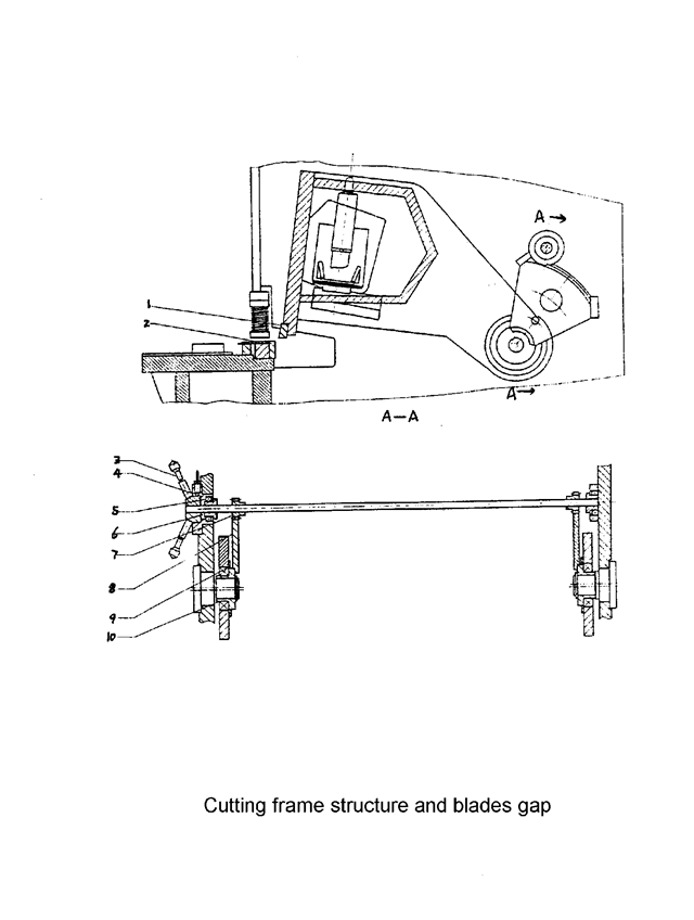
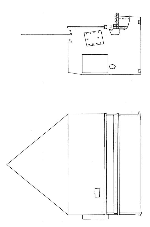
2.2 Cutting frame
Welded plate, high rigidity, is support at eccentric socket (9), by left and right cylinders and stroke cylinder drive, finish cutting by pendulum repeat. (See Fig. 1)
The vertical surface of up-cut support is curve, keep the gap between up-cut and low-cut coincidence.
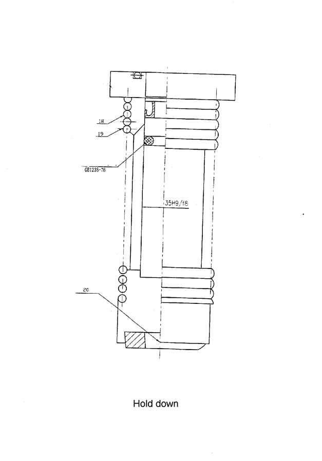
2.3 Pressure device (Hold down)
It is consisted of some pressure feed cylinders installed at support board in front of machine frame. Oil flow in pressure feed cylinder, pressure head press down against the pull force of stress spring (18), press plate tightly. Finish cutting, the cylinders are reset by the pull force of stress spring. The pressure is bigger as thicker as the thickness of plate. (See Fig. 3)
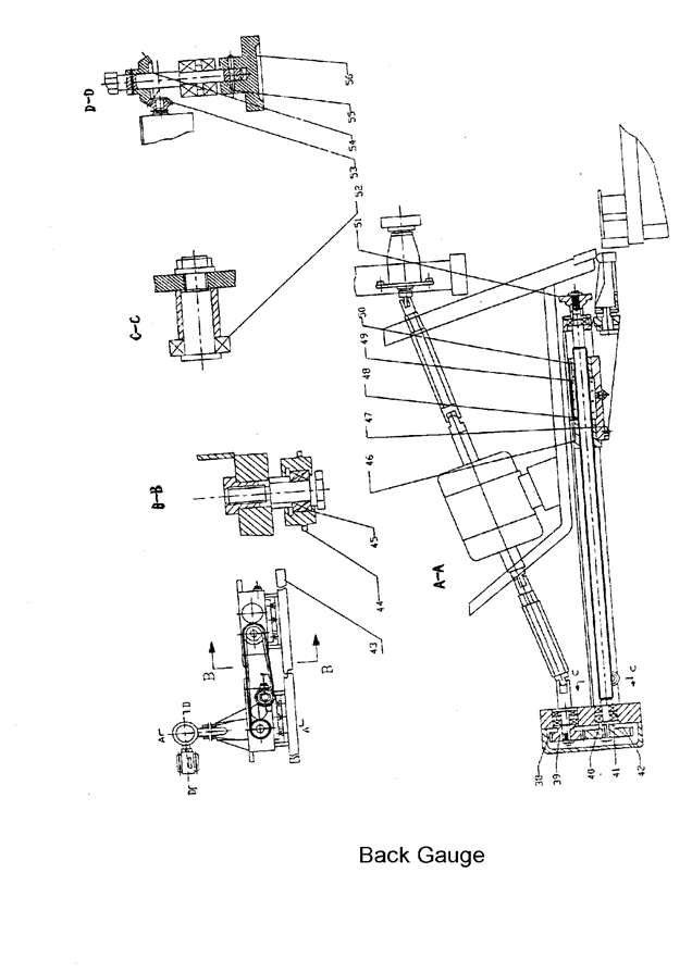
2.4 Front gauge and back gauge
Front gauge: fixed on worktable, valve display on ruler, adjust mobile bar to necessity valve. When cut thin steel plate, cut it conveniently on front gauge.
Back gauge (see picture5) fixed on up-cut board, pendulum up and down as up-cut board. Adjust back gauge by 0.55Kw motor, reduce through gear, and drive by control rod. Brake down the button “+” (or”_”), can adjust gauge to front or back. When mechanic adjustment cannot get the necessity valve, turn hand-wheel (50) to demand valve, the adjustment of back gauge is convenient and reliability.
The standard range of back gauge is 20-750mm. When the length of cutting plate is longer than the max distance of back gauge, remove the back gauge (43) to the least place, lift up the board by the incline surface of support frame (47), then can cut any length of plate. (See Fig. 4)
3.1 Packing / Shipment of machine
All machines leaving the factory are packed with squaring arm and foot panel tied to the hand guard. Working tools and operation manual are packed into one box.
All exposed surfaces on machine are coated with rust guard, easily removable by kerosene or solvent.
3.2 Lifting the machine
Use only approved and safe wire rope to lift this machine from two lifting point which is located at both side frame of the machine. (See Fig. 5)
3.3 Foundation
All our shears are designed to use the foundation. Details please check the attached foundation drawing.
3.4 Installation
This machine must be properly leveled to give a good cut. Leveling is done by putting a good leveling gauge at the plate hold down area. Always pre-prepare five pieces of base plate (dimension 150 x 150 x 9mm, minimum) below machine footing to prevent leveling screw from digging into the concrete floor.
On completion of leveling, a cement grout mixture must be packed under and around the feet to maintain correct leveled position.
3.5 Electrical Installation
Be sure that the local power supply is suitable for this machine before any electrical power up. Connect power cable into the bottom left of electrical panel.
Some machine may require N (Neutral) wire.
4.1 The following steps are to be cared for by the owner and must be carried out by specialized personnel.
4.2 All the operating buttons fixed on controller panel at front except foot switch SF. The symbol of each function is displayed on the above of buttons.
Detail operation steps of digial display system as follows:
Open the door of electric box, close the power switch QF1, QF2, machine is wiring on,close the electric box. Push the key button SA1 ( ), switch on the control circuit. Indicating light HL1 ( ) lighting, shows the machine power on.
Push button SB4 or SB5 (), can run the back gauge to front or go back. The position of back gauge displayed on the SICK mechanical displayer, at the max. and min. travel of back gauge, installed limit switches (SQ3 SQ4), standard max. travel is 500mm-750mm; min travel is 20mm.
Push lighting button SB3 (), lighting shows the pump motor start to work, at the same time, you can hear the working voice .
Switch the button SA3 (), select cutting mode. At (), it is manual mode. At (), it is auto mode.
( ) is the Illumination Light. Turn SA4 to (1), start to count. To (0) place, stop counting.
5.1 Clean the hydraulic Oil
The hydraulic system has high requirement for the cleanliness of hydraulic oil. The clean of oil tank is very important.
When replace the hydraulic oil, you must discharge the cover of oil tank. Use the towel to clean the bottom of tank (do not use cotton yarn), then wash with cleaning coal oil gasoline. For limitation of tank cover, the arm cannot reach the end of tank; you can wrap the towel on the bamboo or stick to wipe each corner. Loosen the leaking plug or brake valve to leak out the dirt oil.
Use the cleaning towel to dry the sides and bottom of tank until it’s clean. If necessary, roll the dough at the welding seam or difficult cleaning places to cling the dirt, and then put on the cover.
5.2 Choose the hydraulic oil
The mark value of hydraulic oil is equal to the average value of viscosity, when the temperature is 40℃.
If the working pressure and temperature of hydraulic system is higher, and the working speed is slower, the chose hydraulic oil mark is higher.
It is recommended to use antiwar hydraulic oil ISO VG46# (the average value of viscosity is 46mm2/s, when the temperature is 40℃). If the machine operates under 5℃ for a long period, you can choose hydraulic oil ISO VG32#.
It is also recommended not to use the machine at very low temperatures (below -5°). However, should this occur, and then let the machine run idle for a while. An oil heater can be fitted in circuit if required.
Under the normal working conditions the oil temperature must not exceed 70C. Under special conditions, oil cooler can be fitted necessary.
5.3 Fill the oil
The using oil must clean. Screw the nut of air filter, filling through air filter. If using the filling equipment with filter, you can open the cover of oil tank and fill directly. Observe oil gauge, when ram stops at Top Dead Spot, the hydraulic oil fills at 80~90% of interspaces.
Make the machine work, first idling then at maximum stroke to expel any air bubbles in the hydraulic circuit.
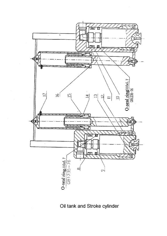
The hydraulic system’s working rule as follows:
The cutting frame goes down:
When the magnetic discharge valve 3 is electricity working on, the hydraulic oil drawed out by pump 2 and flows through magnetic discharge valve 3, go into the hold downs and the up-area of main oil cylinder, the piston of hold downs go down to press the metal-plate after againsted the pull force of the spring, and the oil pressure starts to rise. When the pressure get against the nitrogen gas pressure in stroke cylinder, cutting frame goes down to cut.
The cutting frame return up:
When up-cut frame go down at down-dead spot, magnetic iron YV1 of magnetic discharge valve 3 lost electricity by limit switch, the cutting frame go up by the pressure from nitrogen gas cylinder. At the same time oil of up-area in the main cylinder flow back oil tank through magnetic discharge valve. Also the piston of hold downs go up by the pull force of the spring and oil return back to oil tank through magnetic discharge valve 3. When the cutting frame come at up-dead spot, one cutting is finished.
Hydraulic parts list:
| No. | Name | Specification | Type | Note |
| 1 | Net oil filter | Q=160L/min | Wu-160*100-J | |
| 2 | Gear pump | NB3-G F | Work pressure 18 MPa | |
| 3 | Combinated valve | |||
| 4 | Pressure meter switch | P=32Mpa,d=8mm | KZF-L8H-S | |
| 5 | Pressure meter | P=25Mpa, d=100mm | Y-100-NZh | |
| 6 | Magnetic exchange valve | P=312.5Mpa, d=8mm | SWH-G02-B2-E24-20 | Jining |
| 7 | Ball valve | P=32Mpa, d=15mm | CJZQ-H15L | |
| 8 | Discharge valve | P=31.5Mpa, d=6mm | F2ZB-H16F-4 | |
| 9 | Supply gas valve | |||
| 10 | Pressure meter | P=16MPa | Y-60-NZh |
| 6.1 | Start button | : | To start the main motor running and Control circuit. |
| 6.2 | Stop button | : | To stop the main motor running and Control circuit. |
| 6.3 | Auto/Man mode selector switch | : | Select the working mode |
| In Auto mode | |||
| -One step on the foot switch, the cutting frame will cut continues. | |||
| -Can command cut by foot pedal only. | |||
| In Manual mode | |||
| -One step the foot switch, the cutting frame will only do once cutting. | |||
| -Adjust the cutting stroke by return the rotating button on the panel. | |||
| 6.4 | Foot pedal | : | Push to command cutting blade down and release to have top blade carrier rise in AUTO mode. |
| 6.5 | Illumination Light | : | Working light to shine at cutting blade area, operating at single phase power supply at 220V, 50Hz. |
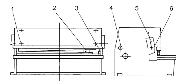
7.1 Adjust the gap between blades
The blade gap is very important on the quality of cutting and the life of blades, please according to the gap adjusting table below.
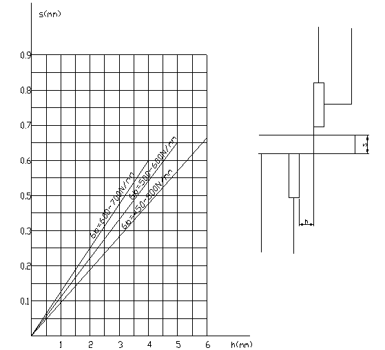
When adjusting the gap (see picture 2), need to loose the tight screw (4), then turn the hand-wheel (3) to the requested value after calculated by the thickness of plate, then tight (4).
There is a ball valve (on right side of machine, out side of cylinder). It is used to measure the coincidence gap between up and low blade.
Detail ways: at manual mode, when cutting frame go to down-dead spot, close the oil circuit rapidly, the cutting frame will stay at down-dead spot, then turn on the ball valve a little by a little, the cutting frame will go up step by step on the all stroke. And then can measure the coincidence value of gap between blades.
7.2 Operation
7.2.1 Preparation of machine
(1) Remove the squaring arm and foot pedal from hand guard area. Set up the squaring arm on left hand side (Close to electrical panel) by bolting down to the machine table and two side holes.
(2) Clear the dirty oil on components, pay attention that the ball valve should be at open position.
(3) Lubricate all the necessary spots.
(4) Supply HL46 hydraulic oil in oil tank (about 200L each machine under 12mm model).
(5) Connect the earth line, switch on, and check the working action of all electrics.
7.2.2 Starting the machine
Push ‘START’ button and release.
Motor “on” indicator light turns on.
Put mode selector from MAN to AUTO position.
Step the foot switch, the cutting frame will go down to cut.
If not, that means motor is running in wrong direction. Switch off power supply. Reverse starts motor again, any of the two phase wires.
The top blade carrier will rise and stop when it hit limit switch.
7.2.3 Motorized Back gauge
The motorized back gauge readout is accurately set in factory and it should be corresponds to the distance measure from back gauge bar to the cutting edge.
Push ‘+’ button to bring back gauge bar to the rear, reading is increase and stops when hitting maximum travel limit switch L/S 3.
Push ‘-’button to bring back gauge bar to the front, reading is decrease and stops when hitting minimum travel limit switch L/S 4.
The parallelism of back gauge is set in factory; however it can be calibrated when necessary.
Bring back gauge bar to the rear for removing anti-rust coating prior to cutting.
Note: (1) The pressure table should be on during cutting, and check the pressure, if it shows wrong, may adjust the overflow valve.
(2) During the operation, if there is deviant noise or the oil tank over temperature, should stop the machine immediately, and the temperature of the oil tank should not exceed 60℃
The fault and resolve of hydraulic system
| Fault | Cause | Resolve |
| Hydraulic system no pressure and cutting frame no action | 1. The plug of magnetic exchange valve is badly connection. 2. The valve core is jammed by waste or becoming rude. All throttle valve hole of coincidence valve cannot flow. | 1. Inspect the plug. 2. Disassemble the valve and clean. |
| 1.Cutting frame return slowly or cannot go up at up-dead spot 2. The action of cutting frame and hold downs is inharmonious
| The pressure of nitrogen gas is not enough. | Supply nitrogen gas for adding pressure |
9.1 Lubrication and Hydraulic Oil
This machine uses hydraulic oil grade 46, refill or replace only with same grade of oil as follow:
FIAT-HTF 46, ENERGOL HLP 46, ESSO NUTO H46, SHELL-TELLUS S68, TOTAL-AZOLLA 46
9.2 Lubrication program
| No. | name | flow | Internal time(h) | Kind and type brand |
| 1 | A top point and a bottom point on each return cylinder. | Small | 16 | Ca-lubrication Oil ZG-3 GB491-65 Mechanical oil N46GB443-84B |
| 2 | A point on the left and a point on the right of the rear stop sliding nut | Medium | 8 | |
| 3 | Two fulcrums for the oscillation of the upper knife frame, one on the left and other on the right | Small | 24 | |
| 4 | One on the left and the other on the right of the clearance shaft sleeve | Small | 48 | |
| 5 | Each spot on piston rod of left and right cylinders | Medium | 8 | 4# carbon-lithium Q/SY1000-65 |
| 6 | Each one on the padding block of the left and right cylinder | Medium | 8 |
Note: 1. Ca-Lubrication 50%, mechanical oil 50%, mixing for use.
9.3 Changing of Shear Blade
Both top and bottom shear blades are identical and inter changeable. Use the ball vale to make the cutting frame go down at the lower dead spot,
The OFF the machine. Remove bottom blade first then the top blade.
Release all small set screw on top blade carrier.
Clean blades and blade housing / sitting.
Fix back top blade first then bottom blade.
Tighten the small sets screw on top blade carrier if necessary to close in blade clearance.
Remember to check for minimum clearance, adjust small set screw to close up blades when require.
CAUTION: Always engages a qualified and experiences personnel to do this job, otherwise damage to shear blades/machine or personnel injuries may result.
9.4 Grinding of Shear Blade
The Shear blade is rectangular in shape and the upper blade has two cutting edges, the lower blade has four cutting edges.
Only after all two edges or four edges are used up then you require regrinding of blade.
REMEMBER: Grind only the thickness and not the height of blade.
May require to close in top blade carrier by screw in tensioning bolt as a result of the loss of Grind-off thickness of the shear blades. (next to quick blade clearance lever).
9.5 Upper and lower blades (Tooling drawings See the attached drawings)
Note!
—The section is used in the machine with special demands, it is only reference to other machines.
For preventing the safety of people and equipment, we design the safety equipment. Operator must not change, remove or discharge the safety equipment.
10.1 Light Beam/Laser Beam
There is a light beam or laser (according to customer’s request), If the operator wards off the light of curtain, the safety module will work. The ram cannot move downward. To avoid the operator injured.
10.2 Safety grid
There is safety grid at side and back of machine. It can keep the operator away from dangerous areas. Safety grid connects electrical system by safety switch. When opens the safety grid, the electrical system starts, the machine cannot operate.
10.3 Emergency stop
There is an emergency stop button on the handle control station, hanging control station. When there happens error operation or other accidents, push the emergency stop button, the machine will stop all actions.
10.4 Hydraulic system
Ram’s falling is very dangerous. To avoid its falling, the system adds the safety lifting valve. The valve cores of exchanging valve and safety lifting valve have checking signal. If the valve core is abnormal, the checking signal will stop the electrical system to avoid the falling injury.
If the valve cores of exchanging valve and safety lifting valve cannot reset, check the valve.
10.5 Troubleshoot
The normal operation is safety.
If it happens any strange accidents, or when you maintain or repair the machine, you lock in the safety grid, push the emergency stop button, which inside the uprights, then call for help.
If your hands or other parts of body are clamps by the punch or sheet, push the emergency button; check the condition then restarts the machine. Switch the operating mode to “inch” position.
Then pushes the handle return button, the ram returns, pulls the clamped parts out.
11.Certificate of Conformity
Hydraulic Shearing Machine
The Machine Is Certificated, Permit to delivery out of the factory.
Pre-adjust inspection
| No. | graph | Inspection program | Permission error | Inspection tools | Real value | Inspection ways |
| G1 | 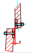 | Coincidence gap between blade and sharp | 0.06 I class 0.10/1000 II class 0.02/1000 III class 0.50/1000 | Clearance gauge | When blade board move between up and down blade coincidence, if two gap of two section is equal, from 50mm, measure the gap & per 150mm. The error is max gap value minus min gap value. | |
| G2 | 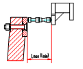 | Parallelism Between low-blade and back gauge | I class 0.10/1000 II class 0.02/1000 III class 0.50/1000 | Clearance gauge inside diameter micrometer | Adjust the mouth of front feed clamp to max or min, measure the distance between back gauge and low-blade, at least 3 spot per one meter, error value is max reading per one meter. |
| No. | graph | Inspection program | Permission error | Inspection tools | Real value | Inspection ways |
| P1 | 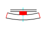 | linearity | 0.25/1000 | Level ruler level table clearance gauge | Put test pieces on level table, 1000mm length level ruler depend on cutting surface of test pieces, measure the gap by clearance gauge. Error is max reading value. | |
| P2 |  | Parrel | 0.15/1000 | Vernier slide calliper | Measure the width of test pieces by vernier slide calliper(at least 3spot per one meter), error is max reading value on any 1000mm. |
Note:
1.the accuracy test duty according to this rule is not real test duty. For fix and dismantle inspection tools conveniently, can be according to any duty.
Demand of test pieces to work accuracy
iii) At 10 times as thickness from section, need not test.
![]()
Masters in industrial manufacturing with 25 years of experience and 10+ awards!