Krrass customer support team is here to answer your questions. Ask us anything!
Hi, how can I help?
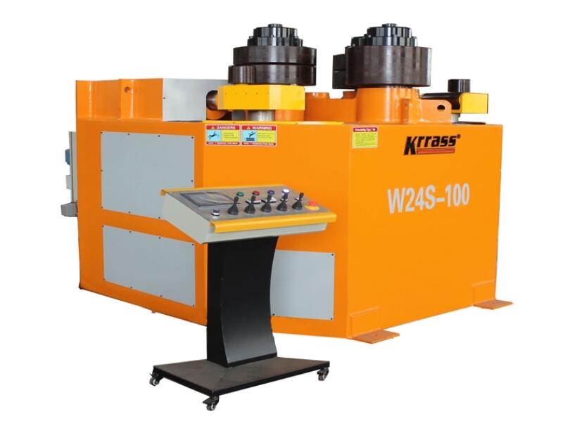
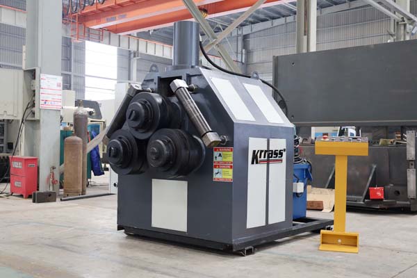
Model:W11S
Controller:PLC
Capabilities:6-300mm
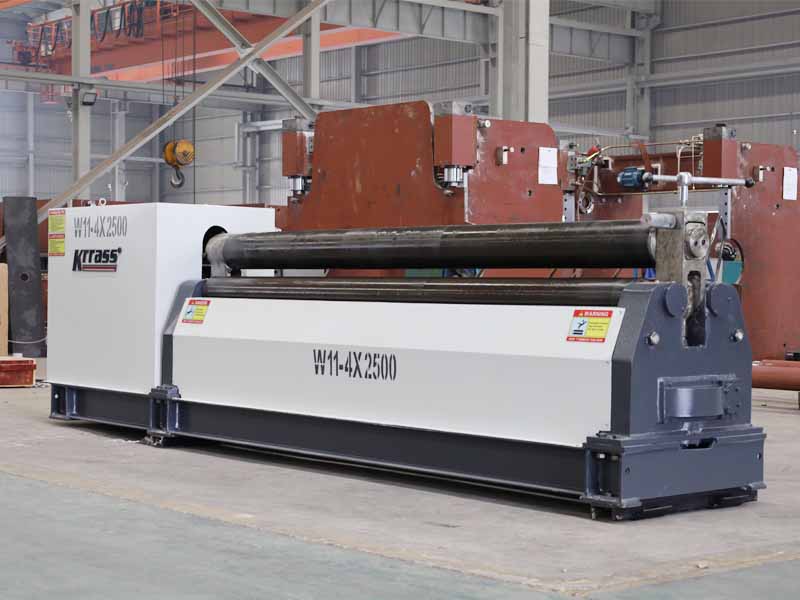
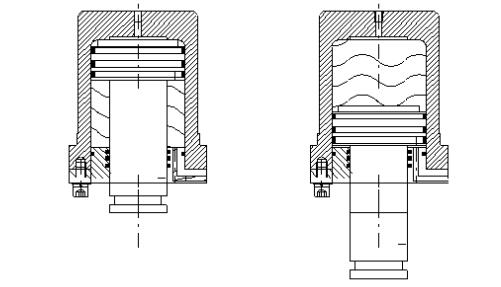
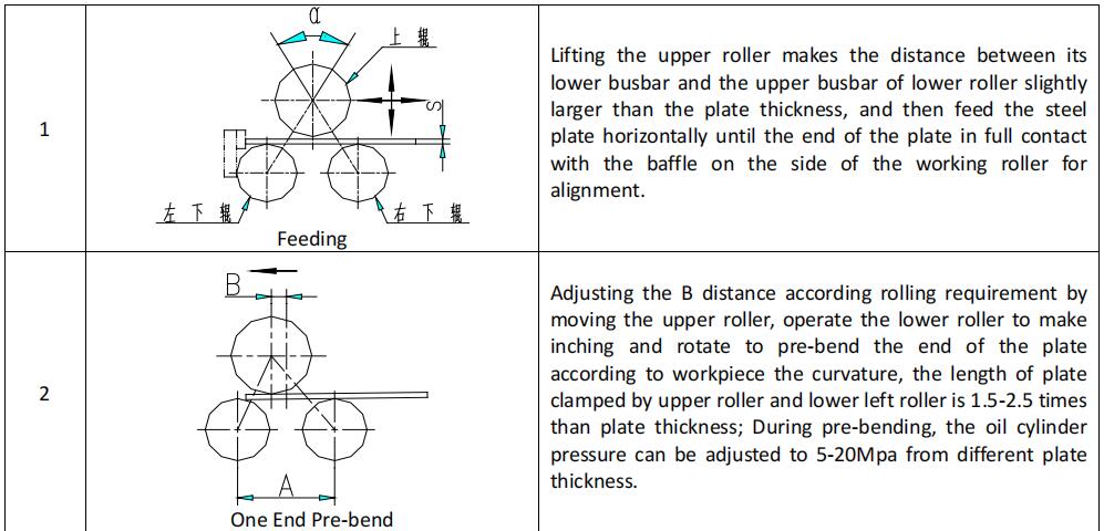
The main structure of the machine is composed of the upper roller device, the upper roller lifting device, the lower roller device, the upper roller horizontal moving device, the supporting roller device, the main driving device and the left and right side frame, the bottom basin and the balance device. The upper roller device is composed of main oil cylinder, upper roller bearing seat, upper roller and double row adjustable center bearing. The main oil cylinder and piston rod are all 45# forgings, the inner surface of cylinder is calenderized, and the piston rod is plated with Cr. The
sealing element adopts Yx type sealing ring imported from Japan, which provides the pressure needed for rolling plate by rodless cavity. The piston rod of the main cylinder is connected with the bearing seat of the upper roller. As shown in the figure:
Generally, the load coefficient of the upper roller pressure is 0.7.The roller hardness processing steps can be divided into two steps, the tempering and hardening hardness is HB240-280 and surface medium frequency quenching HRC45-52, as shown in the figure: The two ends of upper roller are equipped with double row center-adjustable bearing. Double row and double row aligning bearings are arranged in upper roller bearing seats at both ends (Wafangdianbearing), as shown in the figure:
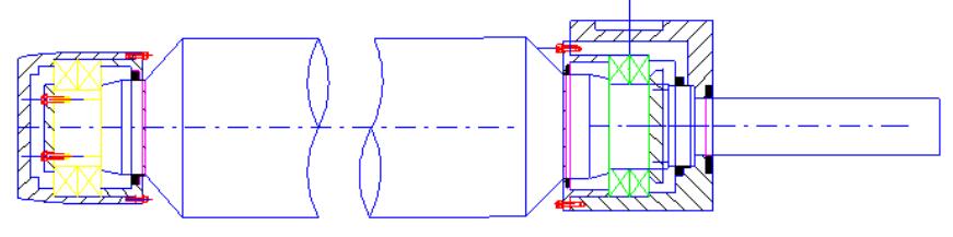
The upper roller is driven by two oil cylinders, with the highest working pressure of 19.5mpa. The upper roller is equipped with rolling bearings at both ends, and the bearing seat moves up and down along the guide rail. The bearing seat at both ends is equipped with displacement sensors to display the movement amount and readout in digital display
meter.
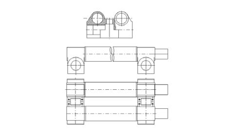
Lower roller device is formed by the lower roller, bearing seat, input gear, sliding bearing and so on, through the main transmission output gear ֽ lower roller input gear ֽ open drive lower roller torque to the lower roller. As shown in the figure:
Horizontal moving device is driven by the transmission motor through worm gear box, worm gear and worm screw mechanism to realize asymmetric rolling. Moving position is displayed in digital display meter.
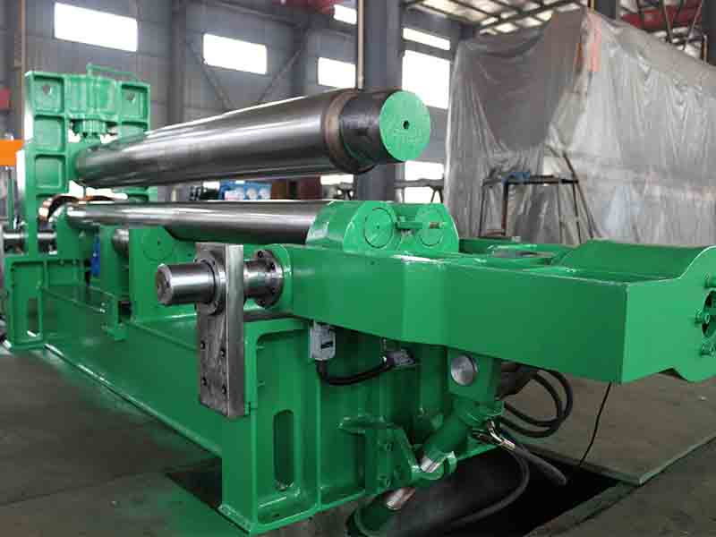
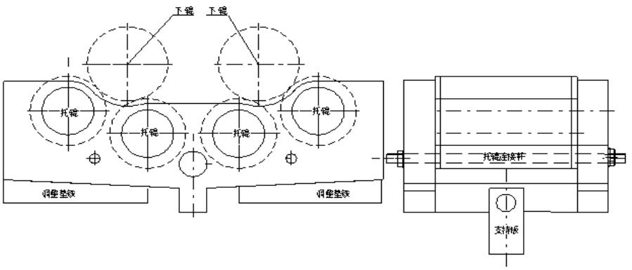
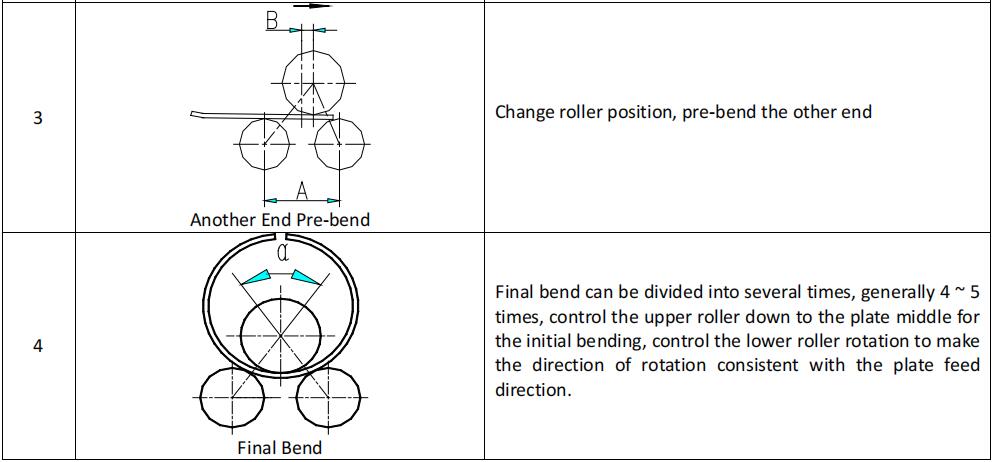
Idler device is composed of screw mechanism, inclined wedge mechanism and idler. Roller is made of 45 # steel, thetempering hardness HB190-220, the surface hardness of idler is lower than that of lower roller, and the idler surface with spiral groove prevent welding slag, oxide skin, mixed skin etc damaging work rollers, and the idler roller can be adjusted up and down according to plate size and load. As shown in the figure:
The main transmission device is composed of main motor and speed reducer. The main transmission can turn in both directions to provide power for rolling plate.
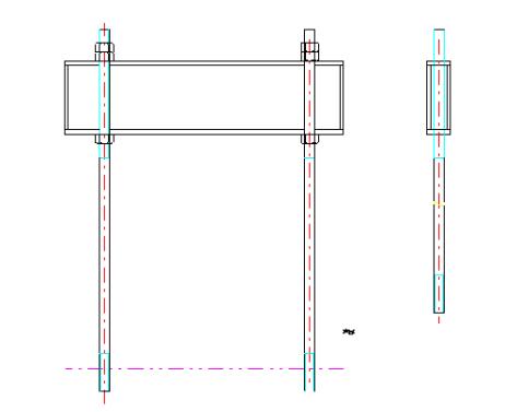
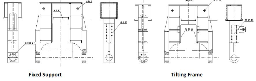
The tilting device is composed of frame, sliding pillow, oil cylinder and pin shaft. Tilting cylinder adopts single stage cylinder and chromium-plated piston rod. The tilting device is used to overturn the side frame, which is convenient for taking out the workpiece. After the frame is repositioned, the next workpiece can be rolled and processed. The cylinder power comes from the hydraulic power station.
Lift the upper roller to a high position and hold it down by the tail of the upper roller. In this way, the upper roller is held down by bearing seat and balance beam to make the upper roller in a balanced state, which is convenient to tip over and close the bearing seat. When the upper roller rises to the highest position, it can be detected by the travel switch. As is shown in the figure:
Frame and chassis adopt frame structure, overall structure, high rigidity, as shown in following figure:
| Model | Pressure of Top Roller | Max. Bending Thickness | Pre-bending Thickness | Max. Bending Width | Top Roller Diameter | Bottom Roller Diameter | Central Distance | Main Motor(Kw) | ||
| Unit/Type | (T) | (mm) | (mm) | (mm) | (mm) | (mm) | (mm) | For Drive | For Hydraulic | For Movement |
| W11S-4x2500 | 25 | 4 | 3.5 | 2500 | 200 | 125 | 160 | 4 | 2.2 | 1.1 |
| W11S-6x2500 | 30 | 6 | 5 | 2500 | 210 | 125 | 160 | 4 | 2.2 | 1.1 |
| W11S-8x2000 | 37 | 8 | 6.5 | 2000 | 210 | 135 | 180 | 4 | 2.2 | 1.1 |
| W11S-8x2500 | 37 | 8 | 6.5 | 2500 | 235 | 135 | 180 | 5.5 | 2.2 | 1.1 |
| W11S-10x2000 | 37 | 10 | 8 | 2000 | 235 | 135 | 180 | 5.5 | 2.2 | 1.1 |
| W11S-10x2500 | 55 | 10 | 8 | 2500 | 250 | 145 | 200 | 7.5 | 4 | 1.1 |
| W11S-12x2000 | 65 | 12 | 10 | 2000 | 250 | 145 | 200 | 7.5 | 4 | 1.1 |
| W11S-12x2500 | 75 | 12 | 10 | 2500 | 265 | 145 | 200 | 7.5 | 4 | 1.5 |
| W11S-12x3000 | 75 | 12 | 10 | 3000 | 290 | 150 | 245 | 11 | 4 | 1.5 |
| W11S-16x2000 | 75 | 16 | 13 | 2000 | 265 | 150 | 245 | 7.5 | 4 | 1.5 |
| W11S-16x2500 | 100 | 16 | 13 | 2500 | 300 | 165 | 270 | 15 | 5.5 | 1.5 |
| W11S-16x3000 | 130 | 16 | 13 | 3000 | 330 | 180 | 300 | 15 | 5.5 | 2.2 |
| W11S-20x2000 | 100 | 20 | 16 | 2000 | 300 | 165 | 270 | 15 | 5.5 | 1.5 |
| W11S-20x2500 | 130 | 20 | 16 | 2500 | 330 | 180 | 300 | 15 | 5.5 | 2.2 |
| W11S-20x3000 | 160 | 20 | 16 | 3000 | 380 | 200 | 330 | 18.5 | 7.5 | 2.2 |
| W11S-20x4000 | 230 | 20 | 16 | 4000 | 440 | 235 | 380 | 30 | 11 | 4 |
| W11S-25x2500 | 190 | 25 | 20 | 2500 | 380 | 220 | 360 | 22 | 7.5 | 4 |
| W11S-25x3000 | 230 | 25 | 20 | 3000 | 410 | 235 | 380 | 30 | 11 | 4 |
| W11S-25x4000 | 270 | 25 | 20 | 4000 | 490 | 250 | 400 | 30 | 11 | 4 |
| W11S-30x2500 | 230 | 30 | 25 | 2500 | 410 | 235 | 380 | 30 | 11 | 4 |
| W11S-30x3000 | 270 | 30 | 25 | 3000 | 450 | 250 | 400 | 30 | 11 | 4 |
| W11S-30x4000 | 380 | 30 | 25 | 4000 | 550 | 275 | 460 | 45 | 22 | 5.5 |
| W11S-35x2500 | 320 | 35 | 28 | 2500 | 450 | 250 | 400 | 30 | 11 | 4 |
| W11S-35x3000 | 380 | 35 | 28 | 3000 | 510 | 275 | 460 | 45 | 22 | 5.5 |
| W11S-40x2500 | 380 | 40 | 32 | 2500 | 500 | 275 | 460 | 45 | 22 | 5.6 |
| W11S-40x3000 | 430 | 40 | 32 | 3000 | 540 | 290 | 500 | 55 | 22 | 7.5 |
| W11S-40x4000 | 540 | 40 | 32 | 4000 | 630 | 340 | 610 | 55 | 22 | 11 |
| W11S-45x3000 | 540 | 45 | 36 | 3000 | 590 | 340 | 610 | 55 | 22 | 11 |
| W11S-50x2500 | 430 | 50 | 40 | 2500 | 580 | 290 | 500 | 55 | 22 | 7.5 |
| W11S-50x3000 | 540 | 50 | 40 | 3000 | 600 | 340 | 610 | 55 | 22 | 11 |
| W11S-50x4000 | 690 | 50 | 40 | 4000 | 700 | 380 | 700 | 75 | 30 | 15 |
| W11S-55x3000 | 610 | 55 | 45 | 3000 | 620 | 360 | 650 | 75 | 30 | 15 |
| W11S-55x4000 | 850 | 55 | 45 | 4000 | 750 | 420 | 780 | 90 | 37 | 15 |
| W11S-60x3000 | 690 | 60 | 50 | 3000 | 650 | 380 | 700 | 75 | 30 | 15 |
| W11S-60x4000 | 930 | 60 | 50 | 4000 | 780 | 440 | 820 | 90 | 37 | 15 |
| W11S-70x3000 | 850 | 70 | 56 | 3000 | 710 | 420 | 780 | 75 | 37 | 15 |
| W11S-70x4000 | 1150 | 70 | 56 | 4000 | 840 | 480 | 920 | 110 | 45 | 18.5 |
| W11S-75x3000 | 930 | 75 | 60 | 3000 | 740 | 440 | 820 | 90 | 37 | 15 |
| W11S-80x3000 | 1050 | 80 | 65 | 3000 | 770 | 460 | 880 | 90 | 37 | 18.5 |
| W11S-90x3000 | 1150 | 90 | 75 | 3000 | 820 | 480 | 920 | 110 | 45 | 18.5 |
| W11S-100x3000 | 1350 | 100 | 80 | 3000 | 860 | 480 | 920 | 110 | 45 | 22 |
| W11S-110x4000 | 1800 | 110 | 90 | 4000 | 950 | 600 | 1120 | 132 | 55 | 37 |
| W11S-120x3000 | 1800 | 120 | 100 | 3000 | 920 | 580 | 1120 | 132 | 55 | 37 |
| W11S-120x4000 | 2300 | 120 | 100 | 4000 | 990 | 640 | 1280 | 275 | 75 | 37 |
| W11S-150x3000 | 2300 | 150 | 120 | 3000 | 1050 | 660 | 1280 | 2x75 | 75 | 45 |
| W11S-160x3000 | 2500 | 160 | 130 | 3000 | 1080 | 700 | 1360 | 2x75 | 75 | 45 |
| W11S-160x4000 | 2800 | 160 | 130 | 4000 | 1260 | 720 | 1380 | 2x90 | 90 | 45 |
![]()
Masters in industrial manufacturing with 25 years of experience and 10+ awards!